DE RE JOYSTICK
Programming & Repairing The First User Friendly Computer Interface
by ADELBERT FERNANDEZ
Everything you ever wanted to know about the classic Atari joystick. How to program it, how to take it apart, how to repair it and where to find one. Also, a BASIC program to control the cursor with your joystick. The program works on all 8-bit Atari computers of any memory size, with disk or cassette. Our title, De Re Joystick, evolved from De Re Atari, a classic Atari reference manual that's unfortunately no longer in print. It described an array of arcane programming procedures--from Player/Missiles to fine scrolling. The strange title literally means "All About Atari." Keep in mind that certin details differ between joysticks--such as the color of the wires and the layout of the circuit board. The principles, however remain the same.--ANTIC ED.
Contrary to the belief of some BASIC programmers, there really is logic to the way the values of joysticks for the Atari are set up. The answer lies in the unusual world of binary numbers.
But first, some foundation. Joystick port 1 is assigned to memory location 632 ($278), which means the status of port one may be found at that location. The full port assignments are as follows:
Port# Memory   Location
  1     632     ($278)
  2     633     ($279)
  3     634     ($27A)
  4     635     ($27B)
(Ports 3 and 4 apply only to the older 400/800 Atari models.)
To find out the status of a joystick port in Atari BASIC, you use the function STICK(n), where n is the port number. Confusingly STICK(0) applies to port 1, STICK(1) to port 2, STICK(2) to port 4, and STICK(3) to port 3. Try this:
10 PRINT STICK(0):GOTO 10
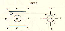
If no one is touching the joystick when you RUN this mini-program, the number 15 should run down the side of the screen. Experimenting with the joystick should give you the results in Figure 1. Try changing the line above to STICK(1). You should now be able to read port number two.
 But we don't need to use the STICK() function. We can go directly to the port location. The above program line can be duplicated like this:
10 PRINT PEEK(632):GOTO 10
So, why did Atari use such strange numbers as 15, 5, 7, 11? To answer, we must dig deeper and comprehend the joystick works. We'll also need to take a closer look at binary numbers.
But don't panic yet! Stick with us. (Sorry about the pun. It just snuck in.)
JOYSTICK TAKE-APART
The more adventurous programmers have, at one time or another, taken their joystick apart. That mysterious black box with the protruding stick can save or destroy millions of beings. (Only in games, of course.)
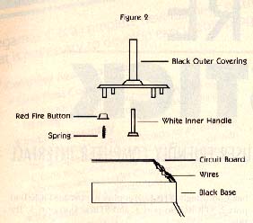
If you haven't stolen a peek inside your joystick, don't get your hopes up. There isn't much to see. They look a little like Figure 2. If and when you do remove those four Phillips-head screws on the bottom, be careful not to lose anything-such as that itty-bitty spring that I lost my first time in. I replaced it with a ball-point pen spring. Just cut off about a third and it works pretty well.
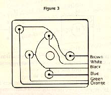
 The part we are interested in is the circuit board--the square fiberboard with the wires attached. (See Figure 3). Notice that the copper lines running across the board eventually end up at the six wires. Five silver buttons accent where the lines meet. Each of these huttons is a switch. When depressed, they complete (close) a circuit.
The black wire is ground. The buttons, in turn, are connected to the other wires, one wire per button and each wire containing +5 volts. So, in theory, the joystick is wired as in Figure 4.
Each switch in this diagram represents a button, and all the buttons are connected to the black wire. When any switch is pressed (closed), the corresponding port pin is grounded (brought "low"), which causes a zero to show up on that pin. The computer senses the voltage loss and puts the appropriate number in the correct memory location.
This process is the same for each button. The orange wire means the fire button has been pressed. The white wire means the top button, the brown is right, the blue down, and the green left. Therefore, when you push up on the joystick, you are actually pushing the top button down, grounding the white wire. Pushing diagonally up and right results in two buttons being pressed, which will ground both the white and brown wires. The computer, sensing this, will place a decimal 10 in the correct memory location. Fire buttons have their own Iocations.
 BINARY STICK
Okay, here it comes. We have to take a peek at some binary number theory here. But we promise not to go very deep. Every memory location (or address) in your Atari contains one byte. Each byte may be a number ranging from 0 to 255 and may be expressed as a decimal, hexadecimal, or binary number. No matter how you and I express it, your computer sees each byte as a binary number.
Binary numbers are expressed solely by means of the digits zero and one. And these digits are called bits. There are eight bits in one byte, and each bit represents a value depending upon its position. These values (read from right to left) range from 1 to 128. See below:
 128  64  32  16  8  4  2  1   value
   0   0   0   0  0  0  0  0   number
The binary byte value 00000001 represents decimal 1. By placing another 1 in the second bit position (remember, reading right to left) and adding the column values in the diagram above, we end up with decimal 3. Binary 00000101 is 5...and so on. Because binary numbers only use two symbols, 0 or 1, these can also be referred to as Off or On. (In computer parlance, when we "set" a bit we turn it On.) Since a computer is nothing more than a complicated series of switches which only understand Off and On, we now see why computers understand binary numbers.
 BACK TO JOYSTICK
Now that we've got that out of the way (still there?) we can examine how the Atari reads the joystick. Since, as mentioned, the computer sees everything as On or Off, we can translate this to 1 or 0.
Your Atari sees the joystick as a series of wires, one fo each direction, and one for the fire button. If the fire button is not being pushed, the computer sees it as "not grounded" and puts a 1 in memory location 644. When the fire button IS pushed, the computer sees it as "grounded" and puts a 0 in 644. And when I say "put", I mean replace. The numbers are replaced when there is a change in condition, not added.
There are four directional wires: Right (brown), Left (green), Down (blue), Up (white)
If none of the buttons are pushed, the computer sees:
1            1             1           1
If the joystick is pushed right:
0            1             1           1
Left:
1            0             1           1
Remember, diagonals are merely two buttons depressed simultaneously.  Stick up and left:
1            0             1           0

Up and right:0   1   1   0
Down and left: 1001
Down and right: 0101
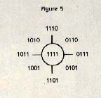 Beginning to look familiar? Take a look at Figure 5. As mentioned, joystick port 1 is location 632. Although this location holds a byte (8 bits) only the first four bits
are used to read the joystick. The other four are unused. (By the way, these four bits, or half-bytes, are referred to as nibbles.)
Beginning to look familiar? Take a look at Figure 5. As mentioned, joystick port 1 is location 632. Although this location holds a byte (8 bits) only the first four bits
are used to read the joystick. The other four are unused. (By the way, these four bits, or half-bytes, are referred to as nibbles.)
To sum up, you push your joystick up and to the right, two switches close and ground their corresponding port pins. This places a pair of zeros in the appropriate locations creating the binary number: 0110, which is stored in location 632 as 00000110. When you PEEK at this location, BASIC coverts the binary number to decimal and prints out a six.
Now that you have the knowledge, use your imagination for the applications. You might design a left-handed joystick, or add pizazz to your programs, or make your games more arcade-style. Finally, these ports can be used as real-world sensors.
Adelbert Femandez is a high school junior from Princeton, West Virginia. He collects Atari computer equipment and back issues of Antic.