DIALOG BOX
CAN'T START WITH START
Could you suggest any books or publications which could help me learn and understand more about my new 1040 ST? This is my first computer. I enjoy reading your articles, but frankly, I don't understand most of them. I wish they were written a bit more clearly so a beginner like me could keep up with them. I realize most of your readers are more informed, but it's very annoying to own a machine with so many things going for it and not be able to utilize it to its fullest.
Patricia Manzo
Winthrop, MA
START's sister publication, Antic magazine, contains a special section called The ST Resource in every issue. Every month the ST Resource includes type-in listings and many short reviews of the hottest new ST software.
The Atari ST for Beginners from Abacus is another good place to start--it begins at the very beginning, with a chapter on setting up your ST. Abacus also offers a complete line of ST books at various technical levels.
Finally, check out the next issue of START for our new column for new ST owners-and anyone else who wants to get the most from an ST!
GFA JOYSTICK ACCESS
I am attempting to find a way to read the joystick with GFA BASIC. Can this be done? Do I need to use joystick "packets," like the ones described inside Atari ST documentation?
David Snyder
Elkhorn, IL
David, it's very easy to access the joystick using GFA BASIC-- just PEEK(&HFFFC02) and you'll have value from the joystick in port 1. The joystick value is a number between 0 and 10. Imagine the joystick as a compass; then N returns 1, S gives 2, W is 4, E is 8, NW is 5, SW is 6, NE is 9, and SE is 10. Zero means the joystick is centered, and 3 or 7 means your joystick is broken--they should never appear. If the firing button is pressed, the number will be higher by 128. (This is the same 1-2-4-8 bit pattern for the N-S-W-E joystick movement that's used on 8-bit Atari computers.)
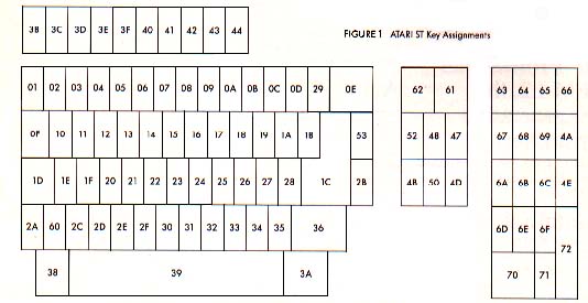
You can also track what's going on with the keyboard and mouse with the same PEEK. Keyboard info comes through in the form of "make" and "break" codes--a "make" code is generated when you press a key, and the "break" code is generated when the key is released. You can tell the "make" code from the "break" code, because the break code has the high bit set--it's 128 higher. Figure 1 shows the "make" codes for the ST keyboard.
Finally, mouse movements are also returned through this PEEK, but they happen so fast they're unusable-instead, use one of the mouse commands available in GFA BASIC (And remember that, while this is a quick-and-dirty way to get joystick and keyboard information, it's not documented, and may not work on future STs.)
HELPING RAY TRACER TRACE RAYS
Help! I've always been able to run the programs in your magazine, but Tom Hudson's Ray Tracing Construction Set (START, Spring 1987) has me stumped. I would greatly appreciate it if you could provide a step-by-step procedure for getting this program to run. My system is a 520 ST with one single-sided drive and a color TV.
Alan Krechman
Tarrytown, NY
Sorry about the confusion, Alan. Here's how to get the Ray Tracer to start producing pictures.
First, uncompress and copy TRACER.PRG and EXAMPLE.CTL to a fresh disk. Then use DEGAS (or a DEGAS-compatible drawing program such as Flicker,from the Summer 1987 START) to create four pictures, one for each wall, and save them as .PI1-type pictures (uncompressed). Copy these four new pictures to the same disk as TRACER.PRG. The Ray Tracing program will supply the checkerboard for the ceiling and floor, and automatically distort the pictures into the correct images for the four walls.
Next, use an ASCII word processor, like 1ST Word or WordWriter ST, to edit the EXAMPLE.CTL file. Look for the line that reads "e:\pictures\lwall.pi1', and change it to the filename of your picture for the left wall. Repeat the process for the other three pictures (change "e:\pictures\rwall.pi1" to the filename for your right wall picture, "e:\pictures\bwall.pi1" to the name of your back wall picture, and ''e:\pictures\fwall.pi1" to the name of your front wall picture). Each picture name appears twice, so be sure you get them all.
After you've changed the wall picture names,find the line that reads "c:\graphics\ray1.pi1" and shorten it to just "ray1.pi1" - then find the line that reads "c:\graphics\ray2.pi1" and shorten it to "ray2.pi1"
Now save the modified EXAMPLE.CTL file to disk. Be sure to save this file in ASCII format. (For example, in 1ST Word make sure WP format is not checkmarked, and with WordWriter save the file as ASCII.)
Finally, put the disk with TRACER.PRG, EXAMPLE.CTL and your four pictures into drive A: and reboot. Double-click on TRACER.PRG, and when the file selector box pops up, click on EXAMPLE.CTL. Be prepared to lose the next four or five hours as you play with the Ray Tracer. Have fun!
WHERE'S MY DISK?
START a magazine with programs on disk. Normally you will find the disk bound into the magazine and selling on the newstands for $14.95.
But some of you ST enthusiasts want to read START first, so we have provided a limited number of copies without disk for $4.00 each.
If this is your situation you can complete your copy of this issue of START by ordering the companion disk direct from us, for $10.95 plus $2.00 shipping and handling. See the order form inserted into this issue.
THE GDOS LOWDOWN
All right. No gobblydegook. I've been reading about GDOS for months, and still don't know what it is! Could you please explain it in simple terms?
Stanley Beck
Chalmette, LA
Stanley, for all the hoopla GDOS (the Graphic Device Operating System) is causing, you'd expect it to be really something, wouldn't you? The truth is there's no magic concerning GDOS, and anybody can understand what it's supposed to do.
When your ST shows you a picture, it's composed of individual dots. That's true whether you're seeing it on a TV screen, a printer or any other output device. How nice an image looks depends directly on how many dots you draw it with--the more dots, the better. The ST monochrome screen shows 80 dots per inch, but a printer can show upwards of 300 dots per inch. (At the really high end, a good plotter or photo-typesetter can get a thousand dots or more in each inch.)
Since your printer can show a much finer resolution picture than your TV can, it makes sense to be able to use the full resolution available for each different output device. That's what GDOS does with a properly written program. The program creates its pictures in an impossibly high resolution, then automatically scales the pictures down to the best resolution possible for your screen or printer.
And that's all there is to GDOS. Period.
NEW YEAR'S RESOLUTION
I am confused about how the resolution of TV monitors is rated. I have seen monitors rated at 400 lines of resolution, while computer makers rate themselves according to how many columns of text they can handle, such as 40 or 80. How are they related? Is there a difference between vertical and horizontal resolution? How does a TV decide how many dots to display?
Dave Wright
Kingston, Tennessee
Dave, TV monitor manufacturers state the capability of their products in units like "vertical lines" or "bandwidth" basically because they don't know beforehand what computer a monitor will be hooked up to. A manufacturer can't actually say a monitor will support 80 columns of text because that depends on how small the computer makes the dots that form each character. To be safe, get the SC1224 Color Monitor Atari supplies for the ST series. If you decide to use another brand of color monitor and you want 80-column color text from your ST, get a monitor with a bandwidth of 10 Mhz or higher. If all you want is 40-column text, including low resolution graphics, any good monochrome or color TV will do fine.
Your last few questions are more involved. We need some basics of NTSC format television signals, used in the Americas and Japan. NTSC television uses 30 frames per second, each with 525 scan lines. The electron beam that creates the picture goes back and forth, from the top of the screen to the bottom. Vertical sync--when the electron beam returns to the top of the screen--runs very close to 60 hertz (times per second, abbreviated Hz). Horizontal sync--when the beam returns to the left side of the screen, also known as the flyback frequency--runs very close to 15,750 Hz. It takes two 60 Hz fields of 2625 scan lines each to build one 525 scan line frame, resulting in an apparent 30 frame per second display. This is just fast enough to fool the eye into seeing smooth movement.
Let's discuss horizontal resolution first. Since we need to show 262.5 scan lines in 1/60th of a second, (.0166666 seconds), we can determine the frequency at which some of the internal TV parts are working. For example, to find out how long it takes to draw each line, we divide the field rate (.01666666 seconds) by the number of scan lines needed per field (262.5), with the answer being very close to 63.5 microseconds (usec).
We may assume that for a dot to appear, we need to turn the electron beam on. For no dot, we turn the scanning beam off. If we plotted the voltage necessary to do this on an oscilloscope, it would represent, in effect, a "square wave" signal.
Now, there is a section of circuitry inside a stock NTSC TV called the intermediate frequency strip, which,for reasons we don't need to get into here, limits the "square wave" (dot/no dot) frequency a standard home TV can pass along to the picture tube to about 4.5 Mhz. This is also known as the "frequency response" or "bandwidth" of the TV receiver. By using the formula from the paragraph above, we find we can turn the scanning beam on and off about 320 times per scan line without pushing the TV too hard. In other words, 320 dots/no dots divided by the time it takes for one scan line (63.5 usec) equals 5.04 Mhz
If, in our computer, we create dot-matrix characters eight dots wide, then we should be able to get 320 dots divided by 8 dots per character, or 40 characters, on each line of a standard TV set. If we try to pump out more dots than this--for example, the 640 dots necessary for 80 characters per line--we would raise the required frequency response to about 10 Mhz. The TV, meanwhile, knows nothing of this and will simply limit the incoming frequency to about 4.5 Mhz. The result is dots that smear against each other, and a quite unreadable display.
So we've determined that basically the frequency response of a TV limits how many dots horizontally the TV can display. Now let's get to vertical resolution. Normally, computer displays don't follow the NTSC standard exactly. For example, NTSC specifies two fields of 262.5 lines each for a 525 line frame. The first field of each pair puts the odd-numbered scan lines on the screen, and the second field puts up the even numbered scan lines. Because the two fields, presented alternately, appear to interlace with each other, this is known as an interlaced picture.
Almost every computer simply puts out two identical fields per frame, noninterlaced, yielding about,200 usable scan lines onscreen. (Some scan lines appear above the top of your screen and some appear below--that's called overscan.) This accounts for why most consumer computers destined to hook up to a NTSC home TV allow a picture of about 320 dots wide by 200 dots (scan lines) high.
To display more dots horizontally, the frequency response of the TV needs to be increased. To get 640 dots or more across on a line, look for a TV or monitor that is rated at 10-15 Mhz rather than the 4.5 Mhz at which a stock television runs. This requires more expensive electronics, resulting in a more expensive TV. To get more dots vertically on the screen, we need to increase the flyback frequency. To get twice as many dots vertically, like the ST's monochrome 400 lines, we need to double the flyback frequency from about 15,750 Hz to around 31.5 Khz. Since we need to draw twice as many lines in the same amount of time per field, we need to draw each line twice as fast as normally.
There's still one other aspect of color TVs that determines just how many dots can show up onscreen. At the front of each color TV is a layer of phosphors, which glow when struck by the scanning electron beam painting your TV picture. The phosphors are usually arranged as triangular groups of red, green, and blue glowing phosphors. To create a white dot onscreen, all three phosphors (red, green, and blue) in that particular triangular group have to be struck by the electron beam at the same fume, thus creating a white dot.
There are TVs with large groups of phosphors, and some with small groups. Naturally, the smaller the grouping, the more dots can appear--but that takes more precise manufacturing, and that's more expensive. The size of the phosphor grouping is expressed as "dot pitch," and typically, for TV sets, runs about .31 to .45 millimeters. For example, this means for a TV set with a ".33" dot pitch, we could expect to get 3 pure white dots per millimeter per scan line. This works out to 30 dots per centimeter, or about 76 dots per inch of TV screen. A 13-inch (diagonal) TV screen is about 10 inches wide; with a dot pitch of 1.33 mm, this should allow us an upper limit of 10 times 76 or 760 dots per line, regardless of the internal electronics of the TV. If the dot pitch is too large, the groupings of RGB phosphors are larger than the dot the TV is trying to draw, resulting in just a portion of the triangular RGB phosphor group--for example, just the red-green or red-blue pairs-being illuminated. (This is one reason why "artifacting" happens on TV screens showing hi-res pictures.)
Some monitors have a dot pitch as small as .16 to .20, with frequency response ranging up to 30 Mhz. To get the best possible picture, buy the highest frequency, smallest dot-pitch TV monitor you can afford.
(Thanks to Mark Sloatman, of Practical Solutions in Tucson, Arizona, for his technical assistance.)