Display Lists Simplified
An important step in understanding your ATARI's graphics capabilities is to create your own custom display lists. This article will show you step-by-step how to mix text and graphics on your TV screen. Our method uses BASIC commands to modify Graphics Modes 0 through 8. BASIC sacrifices some of the ATARI's flexibility; however, these techniques will help you eventually create display lists in assembly language.
The graphics capabilities of the ATARI are controlled by a microprocessor chip called ANTIC (Alpha-Numeric Television Interface Circuit). Any display list is a program for ANTIC.
There is a display list program provided automatically by each BASIC Graphics command, or you can define your own. The display list specifies where screen data is located, what display modes to use, and any special display options ANTIC is to implement. Since the display list describes the screen from top to bottom, any mix of graphics or text modes can be displayed on the screen.
To understand displays, you need to know a bit about television. In a TV, a beam of electrons is shot at the screen. The beam starts at the top left-hand corner and moves across the screen. When it reaches the right-hand side, the beam is turned off, returned to the left, and moved down slightly. It is then turned on again, and the process is repeated 262 times to form a completed screen image.
When the beam reaches the bottom right-hand corner of the screen, it is turned off and returned to the top left-hand corner to start over. These horizontal sweeps are called scan lines and are the basis of the display. The scan-line pattern actually starts above and ends below the physical boundaries of the TV screen. To assure that information is not displayed where you can't see it, the ATARI display usually is restricted to 192 scan lines, positioned in the middle of the screen.
There are several other concepts you will need. These are:
ANTIC MODE NUMBER: ANTIC identifies modes with a set of numbers different from those used by BASIC. The ANTIC mode numbers corresponding to each BASIC Graphics Mode, 0 through 8, are listed in Table 2.
MODE LINE: A mode line is a grouping of scan lines into a fundamental unit for each Graphics Mode. For example, Graphics 8 uses one scan line per mode line; for Graphics 0 there are eight scan lines per mode line. Screen displays are made up of 192 scan lines grouped into mode lines (see Table 2).
LOAD MEMORY SCAN (LMS): The LMS number is the sum of the ANTIC mode number for the first mode line, plus 64. The LMS number has two functions. First, it tells ANTIC what mode will be used for the first mode line of the screen display. Second, LMS instructs ANTIC to take information from the screen memory area of RAM and display it. The next two bytes in the display list following the LMS number give ANTIC the starting address of the screen memory.
DISPLAY LIST POINTER: This is a variable that establishes the memory address for the first line of the display list. This address is found by the BASIC command: PEEK (560)+PEEK(561)*256.
JUMP WHILE VERTICAL BLANK (JVB): This signals ANTIC that the end of the display list has been reached and it must loop back to the beginning. The jump is located immediately following the last mode line of your display list and is indicated by the decimal number 65. The low byte of the return address is given by PEEK (560). The high byte of the return address is given by PEEK(561).
RAM REQUIREMENTS: The Graphics Modes differ in the number of bytes that must be set aside in memory for screen data (see Table 1).
RAM BYTES PER MODE LINE: Just as the Graphics Modes differ in their total RAM needs, they differ in the number of bytes required per mode line (see Table 2). This information is important for synchronizing the Operating System (OS) and ANTIC.
Developing a
Custom Display List
Step 1
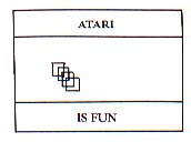
Make a rough sketch of what you want to appear on the screen. Our example appears as Figure 1.
Select the Graphics Modes you want to use and the number of lines for each mode. Two requirements must be met. First, the total number of scan lines in all the mode lines should not exceed 192. If it does, the screen image may roll. However, the total can be less than 192 with no adverse effect. Second, when you insert new mode lines into an existing display list, the total number of bytes required for the inserted lines must be a whole multiple of the bytes required per mode line in the existing display list. To understand this more fully, refer to Figure 2. Diagrams such as this are invaluable in planning a display list.
| RAM Bytes/Mode | Figure 2 | Scanlines |
| 2 x20=40 | GRAPHICS MODE 2 (2 lines) |
2 x 16=32 |
| 40 x 128=5120 | GRAPHICS MODE 8 (128 lines) |
128x1 =128 |
| 4x10=40 | GRAPHICS MODE 1 (4 lines) |
4x8 =32 TOTAL 192 |
Our example will modify a Graphics 8 display list. Each line of Graphics 8 requires 40 bytes of RAM. Therefore, at the top we must insert at least two lines of Mode 2 (two lines x 20 bytes) to match the 40 bytes per line of Mode 8. At the bottom we will insert four lines of Mode 1, each requiring 10 bytes, for a total of 40 bytes.
Matching up the byte requirements between inserted lines and existing lines insures that the text and graphics will appear where we want them.
Step 3
After choosing the modes you want, determine from Table 1 which of them requires the most RAM. Use this mode as your base (existing) mode, onto which you make changes that create your custom display list. This insures that the OS has set aside sufficient memory to hold your screen data. We have chosen Modes 2, 8 and 1. Mode 8 requires the most RAM, so it will be our base mode, called in line 30, but first well write a line to clear the screen and turn off the cursor:
20 ? CHR$(125):POKE 752,1
Next we call the display list to be modified. Adding 16 to GR. 8 eliminates the GR. 0 window that is a normal part of GR. 8.
30 GRAPHICS 8 + 16
We recommend that you enter the program as we go along. It will help you understand the process.
Step 4
PEEK the display list pointer and assign it to a variable such as "DL".
40 DL =PEEK(560) +PEEK(561) * 256 + 4
The number 4 is added to the display list pointer for insurance. Recall that the TV generates scan lines that do not appear on the screen. To allow for this, BASIC Graphics Modes generate 24 blank scan lines at the start of the display list. Adding 4 to the display list pointer will make sure that we don't inadvertantly remove any of these lines.
Step 5
POKE the LMS instruction into DL minus 1. The value 71 derives from ANTIC mode number 7, plus 64. This instruction will establish the first mode line of the display list. If your first mode line belongs to your base mode, skip this step:
50 POKE DL-1,71
Step 6
Every mode line in your diagram requires a statement in your display list. Write these in the same order as they appear on the screen, and POKE the ANTIC mode numbers as appropriate. This is the second line of our Graphics Mode 2.
60 POKE DL+2,7
From the diagram we can see that the next 128 lines are Graphics 8. Since this is our base mode, these lines already exist in the display list. The next mode lines to insert are the four Graphics 1 lines at the bottom.
| 70 POKE DL+132,6 | 80 POKE DL+133,6 |
| 90 POKE DL + 134,6 | 100 POKE DL+135,6 |
| Table 1 | |||
| GRAPHICS MODE RAM REQUIREMENTS | |||
|---|---|---|---|
| MODE | BYTES | MODE | BYTES |
| 8+16 ................. | 8138 | 4 + 16.................. | 696 |
| 8.................... | 8112 | 4.............. | 694 |
| 7+16 ............... | 4200 | 3+16............. | 432 |
| 7....................... | 4190 | 3 ..................... | 434 |
| 6+16 ......................... | 2184 | 2+16..................... | 420 |
| 6................... | 2174 | 2 ................... | 424 |
| 5+16 .................. | 1176 | 1+16................. | 672 |
| 5................... | 1174 | 1...................... | 674 |
| 0................... | 992 | ||
| Table 2 | ||||||
| BASIC MODE NUMBER | ANTIC NUMBER | TYPE | LMS BYTE | # OF MODE LINES | SCAN LINES/ MODE LINE | RAM BYTES/ MODE LINE |
|---|---|---|---|---|---|---|
| 0 | 2 | text | 66 | 24 | 8 | 40 |
| 1 | 6 | text | 70 | 24 | 8 | 20 |
| 2 | 7 | text | 71 | 12 | 16 | 20 |
| 3 | 8 | graphics | 72 | 24 | 8 | 10 |
| 4 | 9 | graphics | 73 | 48 | 4 | 20 |
| 5 | 10 | graphics | 74 | 48 | 4 | 20 |
| 6 | 11 | graphics | 75 | 96 | 2 | 40 |
| 7 | 13 | graphics | 77 | 96 | 2 | 40 |
| 8 | 15 | graphics | 79 | 192 | 1 | 40 |
Step 7
End the display list with a JVB, followed by the low byte and high byte of the return address:
110 POKE DL + 136,65
120 POKE DL + 137,PEEK(560)
130 POKE DL+138,PEEK(561)
140 GOTO 140
Now RUN the program. You will see the top section (GR.2) black, the bottom section (GR.1) black, and the middle section (GR.8) blue. To make the middle section black, change line 30 to:
30 GRAPHICS 8+16:SETCOLOR 2,0,0
Table 3 shows the relevant portions of our display list and demonstrates another important point. Line 30 of our program has stored the LMS instruction in address 32825. Line 40 stores the value 7 in address 32828 to give us the second mode line of Graphics 2. Instructions for the Graphics 1 lines and JVB are stored in addresses 32958 through 32962.
Look at addresses 32921 through 32923. Note that here in the middle of the display list is another LMS instruction followed by a screen memory address! The reason is that ANTIC cannot address a block of memory longer than 4K bytes. Since Graphics 8 requires 8K bytes, the screen memory must be broken up into two blocks. ANTIC is sent to the first block of screen memory by the first LMS instruction in address 32825, and is sent to the second block of screen memory by the second LMS instruction in address 32921. "Jumping the 4K boundary " occurs only for Graphics 8.
You must be careful of two things when you modify a Graphics 8 display list. First, don't clobber the second LMS instruction and the two following bytes by putting mode lines in their place. Second, you must calculate an offset if you change modes after the boundary jump. We did this in line 70, by adding two lines to the display list (DL + 132 vs. DL + 130).
At this point the actual display is written into screen memory. The next task will be to print "ATARI" in the Graphics 2 section. Line 10 established GR. 8 and instructed the OS that data in screen memory is to be interpreted as graphics, not text. Consequently if we simply enter PRINT #6: "ATARI" the OS will not carry out the command. The OS must be told how to interpret the data it finds in screen memory by POKEing the appropriate Graphics Mode number into memory address 87.
140 POKE 87,2
150 POSITION 8,0:PRINT #6; "ATARI"
The OS positions text or graphics on the screen by counting bytes from the start of the screen memory associated with the Graphics Mode value stored in location 87. Thus, it is possible for total screen memory to be considerably longer than the memory for the mode the OS is using. This disparity can cause "cursor out of range" error messages and trouble positioning material on the screen.
The cure for both problems is fairly simple. Before creating a display on the screen, change the start of the screen memory to coincide with the start of the mode section where you want the display to appear. For the Graphics Mode 8 section this will eliminate the trial-and-error method of placement. For the Graphics Mode 1 section this will prevent a "cursor out of range" message.
To write our display we start with:
160 POKE 87,8
to tell the OS what mode we're in. Then locate the current top of the screen address with:
170 TPSCRN=PEEK(88)+PEEK(89)*256
Next, offset the variable TPSCRN by the number of bytes in the Mode 2 lines + 1 (four Mode 2 lines x ten bytes per line = 40 bytes):
180 TPSCRN =TPSCRN +41
Finally, POKE this memory location back into 88 (low byte) and 89 (high byte):
190 POKE 88,TPSCRN-(INT(TPSCRN/256)*256)
200 POKE 89,INT(TPSCRN/256)
This procedure sets up the Graphics 8 section of our display so that the top left-hand corner corresponds to position 0,0. You can appreciate how much simpler it will be to place your display components.
210 COLOR 1 :FOR I = 1 TO 40 STEP 5
220 PLOT 60+I,40+I:DRAWTO 100+I,40+I:DRAWTO 100 +1,80 +I:DRAWTO 60 +1,80 +I:
DRAWTO 60 +1,40 +I
230 NEXT I
Finally, print "IS FUN" in the Mode 1 section at the bottom of the screen.
240 POKE 87,1
250 TPSCRN =TPSCRN + 5121
Line 250 offsets TPSCRN to the beginning of the Mode 1 section. 5121 is obtained from (128 lines of Gr. 8) * (40 bytes per line) = (5120 bytes) + 1.
260 POKE 88,TPSCRN-(INT(TPSCRN/256) * 256)
270 POKE 89,INT(TPSCRN/256)
280 POSITION 6,2:?#6; "IS FUN"
290 GOTO 290
| Table 3 | |||
| ADDRESS | OUR LABEL | VALUE | MEANS |
|---|---|---|---|
| 32822 | DL-4 | 112 | Blank scan lines provide for "overscan" |
| 23 | DL-3 | 112 | |
| 24 | DL-2 | 112 | |
| 25 | DL-l | 71 | LMS-64+ 7 sets ANTIC mode 7 |
| 26 | DL | 80 | and one line of same |
| 27 | DL+1 | 129 | gives address of start of screen |
| 28 | DL+2 | 7 | memory |
| 32829 | DL+3 | 15 | lo-byte +hi-byte*256=33104 sets ANTIC 7 for second mode line (equiv. of GR.2) |
| . | |||
| 32921 | DL+95 | 79 | reverts to |
| 22 | DL+96 | 0 | ANTIC mode 15 LMS and address for |
| 23 | DL+97 | 144 | for 128 4K boundary jump, |
| 32924 | DL+98 | 15 | mode lines includes one line of |
| (equivalent mode 15 | |||
| of GR.8) | |||
| . | |||
| 32957 | DL+131 | 15 | sets ANTIC mode 6 |
| 32958 | DL+132 | 6 | for four lines |
| 59 | DL+133 | 6 | (equivalent of GR.1) |
| 60 | DL+134 | 6 | |
| 61 | DL+135 | 6 | |
| 62 | DL+136 | 65 | JVB to address given by next two |
| 63 | DL+137 | 54 | bytes |
| 32964 | DL+138 | 128 | lo-byte of return address |
| 128*256=32768, hi-byte of return | |||
| address | |||
| +54 | |||
| ___________ | |||
| 32822 = return address | |||
Allan Moose is an associate professor (math/physics) at Southampton College, NY. Marian Loren is a special education teacher for handicapped children in Central Islip, NY. They have been frequent contributors to ANTIC.