HARD-WIRED
Ray Tracing
Hard-Wired Ray Tracing creates complex pictures with multicolored patterns, reflections and movable objects, not unlike the famed "Shiny Bubbles" demo on the Atari ST. This BASIC program works on XL and XE computers with at least 64K memory and disk drive.
If you follow the ST scene, you may have seen Xanth Park's "Shiny Bubbles" demo, or pictures created with Tom Hudson's "Ray-Trace Construction Set" (START, Spring 1987). These images were made using principles of ray tracing, a process now brought to the 8-bit Atari with Hard-Wired Ray Tracing.
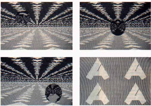
Figure 1 is a series of pictures made with Hard-Wired. Note the reflections of the floor and ceiling on the sphere. The reflections were created with ray tracing algorithms.
The floor and ceiling are actually distorted Micro Illustrator and Micropainter pictures. Hard-Wired shrinks these pictures into little squares, then uses these squares to tile the ceiling and floor. Figure 2 shows the Micro Illustrator picture used to tile the floor.
Our frame of reference is kept as simple as possible by restricting the program to one ceiling, one floor and one sphere. At this level, we only need a tiny set of equations to handle every possible reflection. Hence, the program is called "Hard-Wired" because all of the necessary geometric equations are explicitely defined, or "hard-wired" into the program.
GETTING STARTED
Use your own Micro Illustrator and Micropainter microscreens to create your own ray traced images. You'll need at least two---one for the floor tiles and one for the ceiling tiles. If you want to use pictures created with other paint programs, use the Rapid Graphics Converter (Antic, November 1985) to convert them to a compatible form.
Next, type in Listing 1, HARDWIRE.BAS, checking it with TYPO II, and SAVE a copy before you RUN it.
If you have trouble typing the special characters in lines 2190, 7070-7130 and 8000, don't type them in. Instead, type Listing 2, check it with TYPO II and SAVE a copy. When you RUN Listing 2, it creates these hard-to-type lines and stores them in a file called LINES.LST. To merge the two programs, disk users LOAD "D:HARDWIRE.BAS" and then ENTER "D:LINES.LST." Remember to SAVE the completed program before you RUN it.
When RUN, the program asks several introductory questions, including the position of your eye and the location and size of the sphere.
The first prompt asks you for the coordinates of your viewpoint (the position of your eye relative to the screen.) Under this coordinate system, (0,0) represents the top-left corner of your screen, (319,0) represents the top-right corner, and (319,191) is the bottom-right corner.
The Z-axis runs "through" your monitor. Objects "inside" your monitor have positive Z values; those in front of your monitor have negative values. For example, the coordinates (319,191,-100) name a point 100 units in front of the bottom-right corner of the screen and the point (0,0,0) is on the surface of the screen at the top- left corner.
Type in the coordinates of your viewpoint.
Remember that your viewpoint is always "outside" the monitor, so your Z-coordinate must be negative. Z-values that are very "close" to the screen (between 0 and -200) result in a sphere that looks like an ellipse.
Recommended Z-values are around -450. At this distance, all portions of the screen are relatively the same distance from the viewpoint, and the sphere appears circular.
If you don't know what values to use, press [RETURN] and Hard-Wired will use the center of the screen as your view point.
Next, type in the coordinates of the center of the sphere. Be sure to place the sphere below the ceiling, above the floor, and not too far left or right. Otherwise, it will not be on the screen. Values near the center of the screen work best.
Again, if you don't know what values to use, just press [RETURN] and Hard-wired will place the sphere in the upper-left part of the screen.
Now, type the radius of the sphere. This number must be small enough for the sphere to fit entirely between the ceiling and the floor. Otherwise, the program will print COORD ERROR on the screen and re-prompt for the radius. If you can't think of a value, press [RETURN] and Hard-Wired will calculate a legal one for you.
The next two questions let you move the pictures within the floor and ceiling tiles. If you're creating a series of screens for a "Shiny Bubbles"-style animation, you can use this feature to scroll the floor and ceiling back and forth or side to side. The floor and ceiling move as one; they cannot be moved independently.
If you type 160,0, the image will be moved left, with what would have been the middle of the floor tile moved to the left side of the tile. Typing 0,-95.5 will set the bottom of the screen half a floor tile deeper "into" the image.
Next, Hard-Wired asks if you want to use its Dimming feature. Type Y to use this feature, or N (or [RETURN]) to shut it off.
Finally, Hard-Wired asks you for the microscreens you want to use for the floor and ceiling tiles. You can use Micro-Painter or Micro Illustrator screens. You do not have to type the "D:" prefix when typing their filenames. Once Hard-Wired loads both screens, the screen will go dark and it will begin plotting the ray-traced image.
When it's done, Hard-WIired saves the image to a Micropainter-compatible file called TRACE.PIC. If you want to use a different filename, type it into line 1380.
DIMMING
When light reflects from an object in the real world, part of the light is absorbed and part of it is reflected. This makes the reflected image appear somewhat dimmer.
When you use the Dimming feature, Hard-Wired will dim the rays reflecting off of the sphere. This limits the number of colors you can use in your original microscreens because each each color will require two color registers--one register for the dimmed color and one for the pure color.
Hard-Wired dims the rays by decrementing the color register number. For example, a ray hitting the floor on a pixel with the color in register 3 is reflected from the sphere as the color in register 2. A color in register 0 is reflected as color register 0.
Since Hard-Wired uses GRAPHICS 15, a four-color mode, you may only want to use two of the available colors when drawing your microscreens. Alternatively, you may want to draw your original microscreens with several shades of a single color, such as white, light gray, dark gray and black. If you wish to change the colors that Hard-Wired uses, just alter the SETCOLOR statements in lines 2040-2070.
RAY TRACING 101
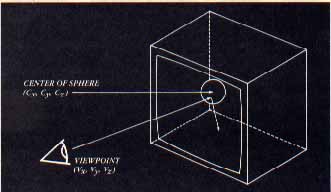
Ray-traced images are made by reversing the path that a ray of light takes to your eye. A diagram of one path that a ray may take is shown in Figure 3. This ray's path begins at your eye (the viewpoint), passes through the screen and into the room containing the sphere.
Once in the room the ray might hit the ceiling, the floor, or the sphere. If the ray hits the sphere, it is reflected onto the floor or the ceiling. In any case, every ray that enters the room eventually lands somewhere on the floor or ceiling.
When the ray lands, the program notes the color of its "point of contact." This color is "mapped" onto the screen at the point where the ray passed through it. If we trace a ray for every point on the screen, eventually we'll have a complete picture.
ANIMATIONS
Once you feel comfortable with Hard-Wired, you can build animations, featuring scrolling floors and moving spheres.
Hard-Wired will not animate your microscreens; you must use a separate animation or page-flipping program instead. MovieMaker will do the job, however you'll have to use Antic's Rapid Graphics Converter to convert your hard-Wired pictures from Micro-Painter to MovieMaker format. Since MovieMaker pictures have half the resolution of Micro-Painter your microscreens will coarser. However, you'll be able to fit twice as many screens into an animation.
There are also many public page-flipping programs. They're also simple to write. See Dave Plotkin's Page Flipping, A Racy Tutorial (Antic, January 1984) and Ian Chadwick's 130XE Memory Management (Antic, November 1985) for information on page-flipping.
Hard-Wired's screen is turned off to hasten the computations by 15 to 30 percent. Press [OPTION] to see the picture as it is being drawn. Using Atari BASIC, each image takes about two hours to calculate. You can achieve much faster speeds with BASIC XE's "FAST" mode or TurboBASIC.
PROGRAM TAKE-APART
Lines 1000 to 1640 contain the "hard-wired" ray-tracing equations needed to map the pixels onto the sphere, floor and ceiling.
Lines 1650 to 1780 use INPUT statements to get the coordinates of the viewpoint and the sphere, the sphere's radius, and the displacemt of the floor and ceiling tiles.
Lines 1880 to 2010 load the two microscreens into RAM. One 8K block of memory is set aside for each screen, and a third block is used to plot the final ray-traced image. All in all, Hard-Wired is manipulating three complete microscreens and three separate display lists.
Hard-Wired finds the spot where the ray hits the floor or ceiling, then uses the LOCATE command to determine the color of the pixel it hit. Hard-Wired then finds the spot where the ray passed through the screen and colors it with this color.
Michael Bjorkman of Seattle, Washington is making his first appearance in Antic.
Listing 1: HARDWIRE.BAS Download
Listing 2: ANTIC.MIC Download
Listing 3: ONE.MIC Download
Listing 4: TWO.MIC Download
Listing 5: THREE.MIC Download
Listing 6: STARS.MIC Download
Executable: FADERII.EXE Download
Listing 7: FADERII.DOC Download / View