WEFAX DECODER
How to use the program, why it works
by PATRICK BASS, Antic ST Program Editor
Before I can teach a computer how to do a job, I must learn that job myself. When I had to put together the software to take the signal from Bill Marquardt's hardware and somehow translate it into an Atari-controlled video picture, I first needed to bury myself in a mountain of information that Charlie Jackson and I had gathered in preparation for this project. There were hundreds of questions needing to be answered--questions as basic as, "What frequencies are the signals transmitted on?"
Finally, after many hours of study and mucho lines of code, this WEFAX decoder program will teach your 8-bit Atari how to display satellite weather photographs from space. (See the ST WEFAX Decoder story in this issue for details about the ST version of this program. -ANTIC ED)
USING THE PROGRAM
(NOTE. This program will not work without the WEFAX Interface hardware described in an adjoining article.) Type in Listing 1, WEFAX.BAS, check it with TYPO II and SAVE a copy before you RUN it. When RUN, WEFAX.BAS creates a machine language file called WEFAX.EXE and writes it to your disk. This is our WEFAX Decoder program. You should copy this file to another disk and name it AUTORUN.SYS. This will be your WEFAX disk. (Antic disk subscribers will find a copy of WEFAX.EXE on the monthly disk.)
Insert your WEFAX disk into yor drive, remove any cartridges from your computer (XL and XE owners should hold down the [OPTION] key), and turn on your computer. The WEFAX program will automatically load and run.
The screen will be mostly white with one text line at the bottom. The text line shows three system values. At the left we have the "K:'' value which shows "line skip," which we'll explain later. The center value shows the width of our scrolling display screen, expressed in pixels. You may change this value by pressing the [<] key to decrement, or [>] to increment the pixel count. At the right of the text line is the number of "clock cycles" to be counted between pixel updates. You may change this value by pressing the [-] key to decrement this value, or the [+] key to increment it.
Next, plug the WEFAX interface into joystick port 2, and plug the interface's audio cable into the audio jack of your shortwave receiver. Plug a joystick into port 1. Tune to some of the frequencies mentioned in this issue's All About WEFAX article, and choose one that gives the strongest, steadiest signal. Adjust your radio's volume to a moderate level.
Now, set the interface's contrast control (R3, on interface diagram) to its halfway point. Slowly adjust the interface's tuning control (R2) until you see the LED flash in time with the chirp of the WEFAX signal. Start the computer scan by pressing the [R] key. Now readjust the interface's contrast control until you get the clearest possible image on the screen.
Once the image begins appearing on your screen, you'll notice a small vertical bar, (about 1/12 the width of your screen) running from the top of your picture down to the current line. This is the image's "dead sector." Ideally, this should be a perfectly vertical strip, aligned with either the left or right margin of the picture. If it's not vertical, use the [<] and [>] keys, as described below, to align the image. If the dead sector is not at one side of your image, use the [A] key to slide it to the left.
With a little practice, you'll quickly learn to synchronize the computer to the incoming signal and produce impressive satellite maps and photos. There is enough time at the beginning of each transmission to make the adjustments needed during the phasing period, and weather transmissions occur regularly. Some WEFAX stations broadcast 24 hours a day. Once you have determined a reliable frequency in your area, it's just a matter of being there at the right time.
DECODER COMMANDS
The WEFAX Decoder program recognizes a number of one-key commands. Their functions are outlined below:
A--Adjusts the WEFAX sync mark to the left a small distance each keypress, allowing you to properly "frame" a WEFAX picture.
R-Resets a picture back to the top.
K--Cycles the line skip counter from zero through nine. This number tells the computer how many lines to skip between each line displayed when receiving a WEFAX picture.
C--Clears the screen.
I--Inverses the image currently on-screen.
L--Loads a WEFAX picture into memory.
S--Saves a picture. You are prompted to select either (Full) WEFAX format with only two pictures per disk, or (Micro) uncompressed 62-sector Micro-Painter format.
1 - Loads in the values for one line-per-second (60 LPM) reception. This covers reception of UPI news photos and some Russian weather satellites (METEOR).
2 Inserts values for a standard two line-per-second (120 LPM) picture.
3--inserts values for capturing two line-per-second pictures in a format only 321 pixels wide, which allows obtaining a full picture in Micro-Painter format.
P--Prints the picture in memory to any Epson compatible printer. The program has been tested on the Star S and D series, Epson and ADS-2000 printers without fail.
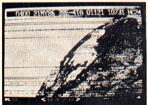
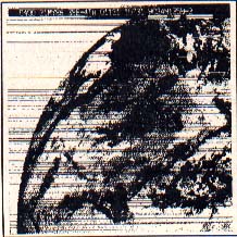
GOES Satellite image (l.) as captured with the 8-bit Wefax Program and (r.) the full image when printed. The horizontal lines are where the signal faded.
SIGNALS FROM SPACE
Just what is it we need to teach the computer to do? A WEFAX picture consists of 800 lines, with each line taking exactly one-half second for transmission. The signal is a musical note which varies smoothly from about 1500 hertz to about 2,300 hertz, where 1500 hertz will produce black, 2300 hertz will produce white and different tones in between produce grays proportional to the signal note itself.
We may consider two different ways to display pictures. One way is a gray scale proportional to the WEFAX tone transmitted. TV weather men capture their weather satellite pictures this way. While the results are very impressive, the hardware interface between the radio receiver and the computer is complicated and expensive.
A second way is to produce a picture using only black and white. The resulting pictures aren't as sharp as the gray scale pictures, but the interface to the radio is simpler and cheaper. We used this approach in developing our WEFAX system.
The interface between the radio and the computer consists of an integrated circuit which "listens" to the incoming musical chirps. Our WEFAX system breaks each half-second chirp into nearly 500 individual tones. One to reproduce a WEFAX picture using at a time, the interface examines each tone and determines if it is above or below about 1900 Hertz (Hz). If the incoming tone is below 1900 Hz, a single output line is pulled LOw. If the incoming tone is above 1900 Hz the output line is driven HIgh. The hardware operates fast enough to follow the incoming signal exactly.
Now, we need to teach the 8-bit Atari to receive, decode, and display each line of incoming picture information. Before we can do this, we must teach the 8-bit Atari to determine exactly when a half-second has elapsed.
HARDWARE TIMERS
There are many ways to do this. But for the high precision we required, the best approach was to use the Atari's hardware timers.
Suppose you were told to ring a bell once a minute while you did something else. It wouldn't make much sense to work while staring at a clock, but what if you hired someone to sit beside you and stare at the clock and tap you on the shoulder whenever a minute had passed. It turns out we can do something like that with the Atari.
Deep inside the POKEY chip there are four hardware timers. We select one of these timers and give it a starting value. Then we teach it to decrement this value once every clock cycle, until the value reaches zero. At this time it will reload the starting value, interrupt the 65O2, and start counting down all over again. We can have the interrupt "tap us on the shoulder" and tell the computer to run our WEFAX plotting routines.
In theory our hardware timers let us come within one-half millionth of a second of precision for timing each half-second interval. In practice this varies somewhat, but the results are quite acceptable.
The default values for a standard two-line-per-second (120 LPM) picture are: 476 pixels wide and 1873 clocks between pixels. Why are these values chosen? Let's do a little math. The Atari 8-bit master clock runs at 1.79 mHz., which means it takes .000000558659217 seconds for each clock "tick". That's a little bit more than one-half millionth of one second. Since we have a screen line 476 pixels wide, and we need to draw each line in one-half of a second, that means we must plot each pixel every .00105042016 seconds--a little bit more than 1/1000 seconds between pixels.
So if we divide the time between pixels (.00105042016 seconds) by the length of one clock cycle (.000000558659217 seconds), our answer (1880) should be how many clock ticks to count between pixel updates. In actual practice, however the value needed is 1873, because the computer uses some clock time to respond to the interrupt itself, and to allow DMA access between ANTIC/GTIA and the main 6502.
PROGRAM TAKE-APART
Now let's wade through the program itself and see what it does. Listing 2 is the master file for FAX.M65, which is written in 6502 assembly language as implemented by Optimized Systems Software's MAC/65. Basically this listing refers to, or "includes," two files from the MAC/65 disk, SYSEQU.M65 and IOMAC.LIB. (These files are not contained on the Antic Monthly Disk.)
Finally, FAX.M65 includes Listing 3, FAXA.M65, which contains the major body of code. You don't need to type in Listing 2 or Listing 3, they are here to help you understand the logic and programming techniques used.
At the top of Listing 3 we have definitions for 9 macros. ADD.W will perform signed, two-byte addition. SUB.W will perform signed, two-byte subtraction. LEA.W will Load the Effective Address (a Word) into the named pointer. MOVE.B and MOVE.W will move a byte and a word, respectively, from one part of memory to another. WRITE will transfer a string of characters to a section of display RAM (such as the screen), performing ATASCII to screen POKE code conversion along the way. MOVEM will move values from multiple memory locations between different areas.
Constant Declarations occur between lines 800 and 1400. We reserve three different sections of memory between lines 1400 and 2350, including space for the text line and the display list. Starting at line 2380, we prepare the Atari to receive WEFAX.
BUILD.LIST dynamically builds a scrolling ANTIC: Mode F (Graphics 8) display list. SCROLL is the routine which keeps track of the joystick and adjusts the display list accordingly. Notice that to scroll the screen, we don't move memory, we move pointers to memory. The INITFAXMAP routine will reset system variables to start-of-picture values, allowing you to receive a new WEFAX picture.
The area between lines 3890 and 4660 is where most of the work is done. Called from the timer interrupt, this section of code plots the dots on your screen. First, the program looks at the input port, joystick port 2. The incoming hit from the interface is wired to bit 7. If the bit is clear, the computer will branch-if-plus. Otherwise, we'll continue on to the LDA #0 and .BYTE GHOST instructions.
What does .BYTE GHOST do? Refer back to the Constant Declarations. GHOST has a value of $2C. In a book on 6502 programming, you'll find that instruction number $2C is the BIT ABSOLUTE instruction, which is three bytes long. Let's examine how this changes the interpretation of the source code.
          BRANCH TAKEN
A9    00   D3    LDA PORTA
10    03         BPL PLT0

A9    00         LDA #0
2C               .BYTE GHOST PLTO
A9    01         LDA #1
. . .            EOR INVMASK . . .

       BRANCH NOT TAKEN
A9    00   D3    LDA PORTA
10    03         BPL PLT0

A9    00         LDA #0
2C    A9   01    BIT $01A9
. . .            EOR INVMASK. . .
From this you can see that if the branch is not taken, the BIT instruction takes the LDA #01 instruction and uses it as the address to BIT from. Since we are not at all interested in the state of memory location $01A9, this test is meaningless to us, and we may ignore the results.
At this point, we have either a zero or a one in the accumulator. Again, we have a zero if the input bit is set, and a one if it is clear. Next, we exclusive-OR this number with INVMASK in case we pressed the [I] key and are running in Inverse video. Then we save the status register, go to the screen, find the bit that COLMASK is working on, and turn that bit off. This is because we assume the dot will be turned off. However, when we pull the status register we check for a value greater than zero. If a such a value is present, we fall through the branch to set (turn on) the appropriate dot. The computer turns on a dot by ORing in the bit value represented by COLMASK.
Next, around line 4110 we finish plotting the dot, and are ready to plot the next one. First, we check to see if ADJCOUNT has a value greater than zero, and if it does, we decrement it. We continue this until ADJCOUNT is equal to zero. This is where we "sync" by sliding the picture to the left.
Whenever you press the [A] key, the program places a small value into ADJCOUNT. This value is automatically decremented, as described above, until it reaches zero. Since we decrement a value instead of selecting the next available point to plot, the dead sector will creep to the left. However, when the value in ADJCOUNT is zero, it is time to select the next available dot.
PROCESS.POINT
Since our scan sweeps from left to right, the first thing we need to do is point at the next column to the right. Then, we compare the new column number with the total number of available columns to determine if we've finished plotting the current line. If so, we branch to PR02, otherwise we select the next column by shifting the bits in COLMASK once to the right. If COLMASK is greater than zero, we branch to the next step in the program. When COLMASK is equal to zero, it's time for a new byte/column. So we reset COLMASK to $80 (the high bit is set), move the value from SPEEDADJ to ADJCOUNT, and then increase the pointer to the current screen byte (POINTER_C) by one.
PR02 AND PR03
When the current horizontal line is finished, it may be time to advance to the next lower line. First we reset COLMASK to $80, move a byte from SPEEDADJ to ADJCOUNT, and then reset the CURRCOL counter to zero. Now, we determine if we have to skip lines onscreen. Pick up SKIPCOUNT. If it is a zero, we branch to PR03. Otherwise, we are skipping lines onscreen, so point back to the start of the line we just drew and decrement SKIPCOUNT to count this line.
The PR03 routine selects the next line to draw on the screen. First, we refresh the SKIPCOUNT from COLSKIP, add 1 to the current row counter, CURRROW, and increase our STARTADR pointer (which points to the start of each line onscreen) by the number of bytes per line, BPL. Next, we refresh our working pointer, POINTER_C, from STARTADR. Next, we compare CURRROW to NUMROW to see if we have reached the total number of rows allowed. If CURRROW is less than NUMROW, we haven't finished yet, so return. Otherwise, our picture is finished, so set STATUS to PIXOVER. This tells the interrupt routine that we're finished.
The next two routines, START.TIMER and STOP.TIMER are fairly straightforward. START.TIMER sets up a sixteen-bit counter from AUDF1 and AUDF2, sets the timer values from TIMERCOUNT, and enables the interrupts. STOP.TIMER sets STATUS to PIXOVER and disables the timer interrupt.
The following routine, PLUTDATA, is the routine which services the timer interrupt. As we enter the routine, our accumulator has already been saved on the stack, so we push the X and Y registers onto the stack and check STATUS. If STATUS is equal to either zero or PIXOVER, we branch out of this routine. However, if STATUS is not equal to PIXSTART, it must be equal to PIXDRAW, so we branch over JSR INITFAXMAP, since this routine is only performed when STATUS is equal to PIXSTART. Then we execute the GETPOINT subroutine described earlier. When we're finished, we leave the interrupt.
The next three subroutines dump the satellite picture to a dot-matrix printer. The PRINTBYTE routine just sends a single byte to the printer. The PRINTFAXMAP routine opens a channel to the printer, configures it for graphics, and then one byte at a time will PRINTALINE until all of the columns are finished.
INIT.SCREEN sets the default values for initializing and coloring the screen. We turn ANTIC off, clear the screen RAM and reset HORIZ.COUNT and VERT.COUNT to zero. Next point to the DISPLAY screen, build our display list and place it where the OS can find it. Finally, we adjust the screen colors and turn ANTIC back on.
DECIMALIZE will convert a binary value in memory locations DECIMAL and DECIMAL + 1 to a four-digit ATASCII number in locations DECIMAL,+1,+2,+3. DEC.TO.ASCII is called from this routine.
Below the decimal conversions, UPDATE.STATS converts three system variables (COLSKIP, NUMCOL and TIMERCOUNT) to ATASCII and places the answers in scratch RAM. Finally, a routine in the WRITE macro will display this information on the screen, performing ATASCII to screen POKE conversions as needed.
The next routines are related: KEYBUFF is a small buffer we use to store keystrokes. KEYTABLE is a table of all the keystroke commands the program recognizes, with LENKEYTABLE keeping track of how many entries there are. KEYJUMPTABLE is a list of subroutines to perform, listed in the same order as the KEYTABLE entries.
MAIN LOGIC
MAIN is the start of program logic. We first INIT.SCREEN, getting it ready to receive pictures, then we complete the job by calling UPDATE.STATS, which shows the statistics along the bottom of the screen. Next, we OPEN a channel to the keyboard and set STATUS to PIXOVER. We start the loop called MAIN1 and try to scroll around the screen, if desired.
Now, we check to see if someone has pressed a key lately. When a key is pressed, the OS deposits the key's hardware value into memory location CH (746, $02FC). We can detect this by checking for a value other than $FF. When one is found, we fall down to the line where we BGET a single character from the KEYBOARD and place it into KEYBUFF.
Next, we check the character against every entry in the KEYTABLE. If there is no match, the character was not recognized, and the computer loops back to MAIN1. Otherwise, the value in the X register will be equal to the number of the desired routine, as listed in KEYJUMPTABLE.
To call a routine from its KEYJUMPTABLE number, we need to double the number in the X register, permitting us to use it as an index into the table of .WORDS which make up KEYJUMPTABLE. Next, we return to the X register, pick up the high and low bytes of the desired address from KEYJUMPTABLE and push them onto the stack. Finally, we perform an RTS. Since we just pushed our own "return" address onto the stack, the 6502 will pull those two bytes off the stack and use them to return to. However, in this case we're returning to someplace we've never been.
SAVING AND LOADING
Our last two routines are SAVE.PIX and LOAD.PIX. SAVE.PIX will let you save either a FULL or MICRO screen. When you save a FULL picture, the entire 30K + scrolling screen is written to disk. Because of the size, you can only fit two FULL pictures on a disk. Thus, you may only save FULL pictures named D:WEFAX.1 and D:WEFAX.2.
The MICRO option only saves the parts of the picture that are visible on the screen. It creates a 62-sector Micro-Painter compatible file called D:PICTURE.
LOAD.PIX will only load FULL pictures. The program will ask you whether you want to load picture 1 or 2. Any other choice drops you out.
Listing1:FAX.EXE Download