HAS YOUR ROBERT HUGGED YOU TODAY
Creating motion in BASIC.
Last month, in "Anatomy of a Robot," we talked about creating motion with your computer. This time, we'll actually do it. We'll need:
- a servo
- a joystick-port connector
- alligator clips or a soldering iron and solder
- a lantern battery and two diodes, or a 5-volt power supply
- an Atari 400/800 computer with BASIC or Forth
Because home computer enthusiasts are not necessarily electronics hackers as well, I'll provide you with as much detail as possible. By following these instructions, you should be able to obtain a simple assortment of parts and to learn an easy way to make them move.
SELECTING A SERVO
A servo is a small, commercially- available plastic box that contains a DC motor, a gear train, and an electronic assembly. Its largest dimension is usually one to three inches, and it has at least one short protrusion, called an output shaft, which rotates when the servo receives the proper signal.
Hobby servos traditionally have been used in radio-controlled (RC) models. The ailerons and landing gear on RC airplanes, the rudders on RC boats, and the steering mechanisms on RC cars are typical applications. Because these models are so popular, it's likely that a nearby hobby shop can sell you a servo. In addition, some of the RC-model magazines can provide you with the names of mail-order houses from which you can order servos and related parts.
When selecting your first servo for robotics, buy the least expensive one you can. You should be able to find a medium-sized assembled servo for around $18, and possibly for a few dollars less if you've got a discounter in town or you order by mail. Unless you an avid tinkerer, you should stay away from build-it-yourself models.
Servos are rarely able to rotate in a complete circle. Instead they typically have a limited "rotary output," which ranges from 90 to 270 degrees. The 180-degree models are the most common and are fine for our purposes.
If you have a choice of connectors on your servo, get the Molex variety. They're less expensive, and you'll probably just cut them off anyway and use the wire ends.
Don't buy "retract" servos - they're only two-position devices. And don't worry about too much torque (turning strength) ratings on your first servo. The garden-variety type has something like 20 ounce-inches of torque, which is about right for operating a gripper. There'll be plenty of time later to spend $50 on a monster with ball-bearing output and enough torque to reel in a bowling ball on a half-inch shaft.
The servos that were tested (at random) with the program in this issue were World, Ram, Kraft, and Royal. There are at least ten other brands available, and any one of them should work as well. Check to see that there are three wires extending from the servo you buy. These are usually red (5-volt input), black (ground), and a third color (pulse input). For the time being, don't get one of the larger five-wire models.
Also, don't rotate the servo's output shaft by hand if you can avoid it. This can create slack in the gear train and result in jittery performance. One final warning: Servos have motors that contain permanent magnets and that generate magnetic fields! Keep them at least three feet from your disks.
JOYSTICK-PORT CONNECTORS
Fortunately, Atari used a standard connector on its joystick ports. We need a DE-9S female, which you have find at many electronics stores. And if you have a surplus electronics store nearby, you may be able to pick up a DE-9S for as little as $.50 to $1.
In fact, you may even be able to find a plain Atari joystick cable - one that has a molded connector at one end and six wires protruding from the other end of a three-foot cable. There seem to be a lot of these around. On such a connector, the wires should be lined up as follows: White-pin 1, blue-2, green-3, brown-4, orange-6, and black-8. This lineup shows that the cable was intended for a joystick rather than a paddle. If available, these surplus connectors may cost only a dollar each. Ask the dealer to let you use an ohmmeter to check continuity, or to allow you to swap if you get a bad cable. It never hurts to mention that you're making a robot.
GETTING 5 VOLTS
As you shop for a servo, you'll notice that they usually specify 4.8 volts. This is because among hobbyists servos are almost always run from four nickel-cadmium or "nicad" batteries in series. Each of these has a voltage of about 1.2 volts under load. A five-volt servo is fine, too, and you can even go up to 5.2 volts. You shouldn't go much higher, though, since we'll be reading a 5-volt logic level from the computer.
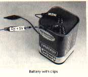
If you already have a regulated 5-volt source with a rating of 300 milliamps or more, you need go no further; if you have four nicads and a charger, you're also in good shape. If not, how about a lantern battery? This power source can be purchased just about anywhere for about $3.00. Even if it isn't one of the more expensive alkaline types, a battery like this will probably last you a week, which is more than enough time to find out if you've caught robot fever.
Since this battery is nominally 6 volts strong, and is actually closer to 6.2 volts in strength when it's fresh and under a light load, we have to "throw away" about a volt. We can do this by putting two diodes in series and connecting the free cathode of the pair (the end without a marking stripe) to the + 6-volt terminal on the battery. The free anode of the pair now becomes the + 5 supply for our servo. This isn't very precise, but it will work. Use 1N4001 diodes, since they're inexpensive and readily available.
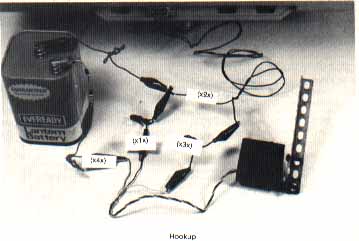
HOOKING UP
The following four connections, each highlighted by "(X#X)" in the text, should be made with the joystick-port connector removed from the computer. Be careful when making these connections. If you misconnect the power supply leads and then plug into your Atari when it is turned off, you can damage the PIA chip. In gelleral, it is best if you plug powered, home-made connectors into your computer only while it is on. The same holds true for unplugging such connectors.
Let's review the pinout on the joystick-port connectors to be sure that we're in step. Facing the port, or looking at the back of a D-9 connector, the pins are numbered like this:
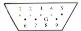
(The pins marked with an "*" can be used for output. We'll be using pin 1 on Port 2.) The proper connections are as follows:
- Ground: The power supply, the servo, and your computer will share a common ground. To accomplish this, we connect the negative terminal of the power supply to the black wire of the servo (X1X), and to pin 8 of the connector (X2X). If you're using a surplus joystick cable, pin 8 should be the black wire; however, it would be best to check this by using an ohmmeter. Remember that the pins facing the front of the molded connector are the mirror image of the above diagram.
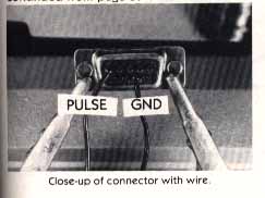
- Servo pulses input: Connect the third wire of the servo (the wire that is neither black nor red) to pin 1 of the connector (X3X). If you're using a molded plug, pin 1 should be the white wire, but (again) double-check with your ohmmeter or another continuity checker to be certain.
- Servo 5-volt connection: Finaly connect the positive end of the 5-volt supply to the red wire of the servo (X4X).
When the wiring has been completed and double-checked, put the assembly aside. We'll type the program in next, and then plug the connector into the joystick port and see what we've got.
DRIVER PROGRAM
As was mentioned in the last issue, we want to set up the driver program as an interrupt-driven, machine-language background task. This will allow BASIC or Forth to run normally as a foreground task, albeit slightly slower than usual.
We want to send the servo a pulse periodically (60 times per second) from pin 1 of Port 2. This pulse should have a width in the range of about one to two msec. We'd like to do this with a relocatable machine-language routine, which we'll call the servo-driver routine. Finally, we'd like to have a simple way to send new orders to the servo-driver routine from our high-level language. Such a BASIC listing is provided at the end of this article. A Forth version, along with some sample programs for both versions, will appear in the next issue.
BASIC LISTING NOTES
Enter the BASIC program and save it to disk or cassette if you have one of these devices. Then plug the joystick-port connector on your servo assembly into Port 2, and RUN. Your servo should now be oscillating between its extremes every four seconds or so. If it isn't oscillating at all, check your wiring again. But if you're getting motion, we can now "tune' the program.
To adjust the program to your particular servo, you must modify two values, the starting point and the width of travel. Press [BREAK] to exit from the oscillation loop and then do a POKE SERVO,0. The servo will probably move once when you do this. We want it to move to its "0" position, which is as far as can go clockwise from your vantage point, facing the output shaft). However, if the program directs the servo to go past its "0" position, it will be under continuous strain, and will vibrate. Touch the servo's case. If you feel any vibration, type in:
POKE OPULSE,PEEK(OPULSE)+2
and check the servo's case again. If it is still vibrating repeat the above line until the vibration stops. Then repeat the line twice to give your servo a little breathing room and then type:
PRINT PEEK(OPULSE)
to get the proper value at location OPULSE. Next, edit line 170 of the BASIC program so that this value is POKEd into OPULSE. This completes the first part of the calibration.
We next want to establish the upper value that we can POKE into SERVO before the servo begins to strain at its other extreme. Start by typing POKE SERVO,150. This should move the servo most of the way around. Now type:
POKE SERVO,PEEK(SERVO)+5
and feel the case to see if the servo has begun to strain yet. Repeat the above line until the case begins to vibrate; then back off a bit by typing:
POKE SERVO,PEEK(SERVO)-2
and repeat this line until the strain is relieved. Then repeat the line twice to provide a margin, as we did a moment ago when setting OPULSE. Then type:
PRINT PEEK(SERVO)
and jot this value down. Edit line 1010 so that this value is assigned to TOP for the oscillation demo. Then type GOTO 1000 to resume the demo, which should now be moving the servo between its extreme points. The range of values that can be POKEd into location SERVO is from 0 to TOP. Other values will either cause the servo to strain or will generate an error condition (if they are outside the range of 0 to 255). Calibration of your servo is now complete. Save your listing.
When you first ran the program, by the way, you actually installed a short machine-language routine. This generated the pulses that the servo needed to see, based on the value POKEd into SERVO. The vertical blank interrupt vector was then pointed to this routine so the appropriate pulses would be generated 60 times per second. This pulse routine is relocatable, and is installed starting at the value assigned to SERVO in line 140. Currently, it is at 1536 decimal, which is the beginning of Page Six of memory (unused by BASIC). If you'd like to store the routine somewhere else, simply change the value in line 140 to the installation address of your choice. Pick an address that is divisible by 256 so the routine won't cross a page boundary - this could alter the timing of several branch instructions, which could, in turn, throw off calibration.
Once the pulse routine has been installed, the whole installation program can be discarded by typing NEW. The only data you need for your subsequent program are the value you assigned to SERVO, which is where you will POKE your position values, and your TOP value for this servo.
Next month we will look at a version of this listing, along with sample programs for BASIC and Forth, and will consider both multiple-servo versions and low-cost sensors.
Evan Rosen is the co-author of Val-FORTH from Valpar International.
Download SERVO.BAS Download