On
Splines
BY DANN PARKS
Gain control over your animations! File SPLINES.ARC on your START disk.
Dynamic Motion
Control with
Cyber Control
One of the most powerful features of Cyber Control is its ability to define a path in 3D-space and then move an object along that path. These paths are called "splines" and they are the "3D" in three-dimensional computer animation. Splines are not useful just for moving objects around. Cameras, lights, viewpoints and practically anything else you can imagine can be moved along splines. Cyber Control allows complete freedom to create splines and to access the points along them.
The easiest way to move an object along a spline is to use a for/to loop, moving the object to the next point on the spline by using the index variable of the loop (this procedure is explained in great detail in the Cyber Control manual). The number of segments into which a spline is divided controls the speed at which an object moves along it. What's missing in Cyber Control is the ability to control the dynamics of movement along the spline, such as acceleration or slowing to a stop. These motion dynamics are known as "slow-in" and "slow-out" and are essential for creating smooth animations.
Problems with VISITORS
I first ran into this problem doing an animation called VISITORS. It
showed a spaceship zooming through a row of columns in a Greek temple.
I wanted the ship to slow down and pass between two columns and then stop
right in front of the camera. The problem was that there was no way to
slow the ship down through the columns, and then the ship stopped very
abruptly at the end of the spline.
I had heard of other solutions, such as creating multiple splines end-to-end, each with a different number of divisions. But that still caused unacceptable jerking motions at the transition points between splines. Then I came upon a solution that was simple, flexible and allowed unlimited control of speed, slow-in, slow-out and even reverse.
The secret turned out to be dividing the spline into 1,000 or more segments. Then all I needed was a way to describe the movement of an object- the spaceship in this case - from one of those points to another. The differences between successive moves would then control speed and create acceleration and deceleration.
Now, there are probably some fancy mathematical formulas that could generate the numbers I was looking for, but I wanted something that didn't require a degree in calculus and could be done entirely in Cyber Control. I also wanted visual feedback as to what was occurring.
Adding a Second Spline
The solution was to use a second "control" spline, a two-dimensional
spline that uses only the x and y positions with the z value held at 0.
It starts at a y = 0 position and ends at a y = 1000 position and has the
same number of segments as the number of frames in the animation. I then
move a "marker" object (a small cube will do) along this spline and use
the GRPCENT command to determine the marker's y-coordinate value. After
that number is changed to an integer, it's used to place the spaceship
on the "movement" spline.
By changing the shape of the control spline, you can alter the dynamics of the spaceship's speed and direction on the movement spline. The ship will still go from one end of the movement spline to the other in the specified number of frames, but how it moves is totally controllable.
The control spline and marker actually run right through the middle of the CAD-3D 2.0 universe, but since the marker is never selected for rendering, the whole process is invisible. However, an interactive system for viewing and manipulating the control spline could be developed.
The concept is not as complex as it sounds. Let's look at a few examples. Copy SPL1NES.ARC and ARCX.TTP from your START disk to a blank, formatted disk and then follow the directions located elsewhere in this issue to un-ARC SPLINES.ARC. This file contains two Cyber Control programs that will build and run examples of each of these splines (MOVEIT.CTL and BOUNCE.CTL), a spline point file (CONTROL.3D2) and a Cyber Control program that lets you see the effects of changing spline point locations (V1EWSPLN.CTL).
How It Works
Figure 1 is an example of a simple slow-in/slow-out control spline
with five control points. As the marker is moved along the spline, the
y-position values are closer together at the ends than in the middle, meaning
that the object on the movement spline will move slower at the start and
end of its travel.
Whether an object accelerates, decelerates, stops or moves smoothly depends upon the orientation of the control spline with respect to the y-axis. When the control spline is perpendicular to the y-axis, the object on the movement spline will not move. When the control spline is parallel to the y-axis, the object on the movement spline will move at a steady speed. When the control spline changes from perpendicular to parallel, as at the beginning of the spline in Figure 1, the object will accelerate. Finally, when the control spline changes from parallel to perpendicular, the object will decelerate.
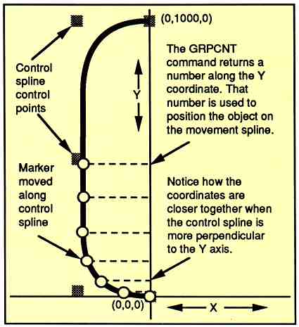
Figure 1. By carefully designing your control spline, you can create
all types of object movements. When the control spline changes from
perpendicular to parallel, as at the beginning of the spline, the
object
will accelerate. Conversely, when the control spline changes from
parallel to perpendicular, the object will decelerate.
Figure 2. This spline causes the object on the
movement spline to accelerate, then slow to a
stop, then accelerate again and make an abrupt
stop at the end of the spline.
Figure 3. This control spline causes the object
on the movement spline to abruptly start and
move along the spline, slow to a stop and then
backup on the spline to an abrupt stop about
halfway along its length.
Figure 4. In the BOUNCE animation, a marker is rotated
through a 180-degree arc with a 0,0,0 center, instead of using
a control spline. The same GRPCENT command is used to
produce a y-coordinate, but instead of using the value to
determine a location on a spline, it is simply used to indicate
the height of the ball above the table.
The control spline in Figure 2 shows a more complex arrangement. This spline causes the object on the movement spline to accelerate, then slow to a stop, then accelerate again and make an abrupt stop at the end of the spline.
Any guesses on Figure 3? Right, it causes the object on the movement spline to abruptly Start and move along the spline, slow to a stop and then backup on the spline to an abrupt stop about halfway along its length. This kind of a movement could be used to make a cartoon car skid to a stop and then snap back.
use a second
"control" spline.
For the VISITORS animation, I used a version of the Figure 2 spline. reversed to make the spaceship slow through the columns, accelerate and slow to a stop in front of the camera.
There are two ways to create control splines. You can specify numeric points in a DEFPT command or you can build a series of "control point markers" (little cubes called box 1., box2, etc.) and use them to define the spline. This method is explained in detail in the Cyber Control manual. The second method also allows you to change the shape of the control spline in an interactive fashion by manipulating the control point markers in CAD-3D 2.0.
Let's Move It, People!
Let's begin with the program MOVEIT.CTL. You will need CAD-3D version
2.0 or later and Cyber Control to use this and the other programs in this
article. MOVEIT.CTL builds animated examples of the movements generated
by the control splines in Figures 1, 2 and 3. It also lets you load CONTROL.3D2,
the control point marker file. These markers can be manipulated in CAD-3D
2.0; VIE WSPLN.CTL lets you view the resultant control spline.
To run MOVEIT, load CAD-3D 2.0 and Cyber Control. Make sure that all four of the un-ARCed files are in the root directory of your A drive and that the watch buffers are enabled. Load MOVEIT.CTL into Cyber Control and click on Run. You'll be prompted to select a control spline. Choices 1, 2 and 3 are examples of the control splines in Figures 1, 2 and 3, respectively. Choice 4 will load the CONTROL.3D2 file. MOVEIT will build a 150K delta animation in the root directory of the A drive, so be sure there's enough room on your disk. Also, each choice will build an animation under its own name, CONTROL1.DLT, CONTROL2.DLT, etc. and each will be about 150K in size.
Ready? Choose 1 and in about 15 minutes you'll have a 60-frame animation ready for viewing in Cyber Paint, Animate, or START's Audio-Video Sequencer (AVS). You'll see a bright red ball moving down a corkscrew-shaped spline. The ball accelerates up to speed and then slows to a stop at the end of its travel; run this animation in pingpong mode to see this more clearly.
Now try choices 2 and 3 and examine the differences.
The control point markers in the CONTROL.3D2 file are set in the same location as those in choice 1 (Figure 1). Load and run VIEWSPLN.CTL to take a look at this control spline.
Peeking at the Control Splines
VIEWSPLN offers several choices. When you first run it, you haven't
shown any splines, so enter 1 to clear the splines. You are next asked
how many frames (spline points) you will want to see; to be consistent,
enter 60. Next, enter 1 to merge in the CONTROL3D2 control points. Finally,
the "Fit View to Screen" question should be answered 2.
add a great amount
of realism to your
animations.
When VIEWSPLN has finished running, you can close the Cyher Control
and click on Superview in
CAD-3D 2.0 to study the spline. The spline control points are red and
the spline points themselves are blue. Every tenth frame point is white
to give you an easy reference.
Now, let's play with it a bit. Enlarge the CAD-3D 2.0 TOP VIEW window to full. The small control point markers, called box 1 thru box 5, should be visible. You can now move any of the markers to any position. Then open up Cyber Control and run VIEWSPLN again. This time, enter a 2 at the first prompt to keep the earlier spline on the screen and use 60 frames. Be sure to answer 2 to the prompt to use existing points and, again, answer 2 to the Fit View to Screen prompt.
When VIEWSPLN has finished, you can check out the spline created by your new control point arrangement. You'll notice that this time, the control points are blue and the spline points are red, so that you can see the differences easily.
Make It Fit
Depending upon how you set the points, your spline may wander off the
visible screen. The Fit view to screen? option sets the camera zoom to
insure that all of the control points are visible on the screen. This is
the subroutine that accomplishes this:
@SETCAM2
group a:allgrp:grpccnt x,y,z
bounds minx.miny. minz,maxx,maxy,maxz
z1=int(130000/abs(maxy-miny))
z2=int(130000/abs(maxx-minx))
cam 2 x,y15000,x,y.z.90
if zl<z2 then zoom z1
if zl>z2 then zoom z2
perspec 0
return
The cost of using the Fit View option is that splines will be shown on the screen in different sizes depending upon where you set the control points. The spline dimensions themselves won't change, only their magnification.
If you want to see what effect your modified control splinc has on the MOVEIT animation, save the modified CONTROL.3D2 file. Be sure that you have copied the original CONTROL.3D2 to a spare disk or modify the pathname or filename in @CONTROL4 to load your new control point file.
Now, run MOVEIT and enter 4 at the prompt. After a little experimentation with the control point file, you should get a feel for the results produced by various spline shapes.
To use this system in your animations, copy the relevant portions of MOVEIT into your .CTL file. The MOVEIT file is heavily commented and the lines marked with an asterisk are the important ones. It helps to have a pretty good working knowledge of Cyber Control or you can make quite a mess. If you're new to Cyber Control, practice making spline animations without the control splines first.
Still Another Technique
The final file in SPLINES.ARC, BOUNCE.CTL, creates a 30-frame, 50K
animation of a ball bouncing on a table. It uses a different application
of the same principle to produce the slowdown effect as the ball reaches
the top of its travel and accelerates down again.
In this example, instead of using a control spline, a marker is rotated through a 180-degree arc with a 0,0,0 center. The same GRPCENT command is used to produce a y-coordinate, but instead of using the number to indicate a place on a spline, it is simply used to indicate the height of the ball above the table. See Figure 4.
As you can see, this is really a simplified double-spline approach. By utilizing the change in the x-coordinate instead of the y-coordinate, it would produce a slow-in, slow-out effect with no steady-state speed. Also, by moving the marker in a full circle and using the y-coordinate, you could make an object (a spaceship or a hummingbird) bob up and down slightly while hovering. Such subtlety can add a great amount of realism to your animations.
Cyber Control is a very powerful animation language and, as you can see, you don't have to be a math whiz to access the subtleties, it just takes some playing around and thinking of the "what if" possibilities.
Dann Parks is the Art Director at KTEH public television in San Jose; California. In addition to using his Atari ST for broadcast animation at the station, he also uses it for MIDI music-making and designing experimental three-wheeled sports cars. The VISITORS animation, an Antic Publishing Hologram Contest winner, and his latest animation, BUZBUZBE, are available in Antic Online on CompuServe (type GO ANTIC).
PRODUCTS MENTIONED
Cyber Studio, Including CAD-3D 2.0, $99.95;
Cyber Control, $89.95;
Cyber Paint, $79.95.
Antic Software, 544 2nd Street, San Francisco, CA 94107, (800) 234-7001.
AVS (Audio-Video Sequencer), START November 1988; for disk only, $10.95 plus $4 shipping and handling; for disk and magazine, $14.95 plus $4 shipping and handling. START Back Issues, 544 2nd Street, San Francisco, CA 94107, (800) 234-7001.