ON DISK!
GFA VECTOR
PROGRAM BY GFA SYSTEMTECHNIK
ARTICLE BY ANDREW REESE, START EDITOR
GFA Vector lets you animate three-dimensional objects in your GFA BASIC programs! GFA Vector runs on either color or monochrome monitors and includes its own object-creation facility. You will need GFA BASIC 2.0 to create your own programs.
Add dazzling 3D animation to your GFA BASlC programs. File VECTOR.ARC on your START disk.
GFA BASIC 2.0 was written by GFA Systemtechnik as the definitive BASIC for the ST. Since its creation, GFA has added a series of complementary modules to make programming in GFA BASIC even more powerful. Through arrangements with GFA and MichTron, we have been able to present GFA BASIC 2.0 and GFA Object in the pages of START in previous issues (and on the companion START disks).
The GFA BASIC 2.0 Interpreter, presented in START in January 1989, is the main program you use to write and run programs. GFA Object, presented in May 1989, is a stand-alone three-dimensional object modeling program that lets you create 3D objects. You can use it to design complex spaceships, for example. GFA Vector, on this issue's START disk, lets you take your spaceships and animate them in real-time in your GFA BASIC programs.
GFA Vector runs on both color and monochrome monitors. You must be in medium resolution on color systems.
In order to make full use of GFA Vector, you will need a copy of GFA BASIC 2.0. If you do not have this interpreter, it is on the January 1989 START disk which you can order from our Disk Desk for only $10.95, plus shipping and handling. You cannot create GFA Vector programs using GFA BASIC 3.0.
Finally, if you want a copy of the original manual for GFA Vector, complete with a tutorial and explanations of all of the machine language routines, we have a limited number available. See the end of this article for details.
Getting Started
GFA Vector is on your START disk in the archive file VECTOR.ARC, which contains the following files:
- GFABASRO.PRG, the GFA BASIC run-only program. This program lets you run your GFA BASIC programs, but not edit them. It may be distributed freely.
- EXAMPLE.BAS, a GFA BASIC 2.0 program that gives an example of GFA Vector's clipping routines. You may load it into the GFA BASIC interpreter to examine the code but you can only run it by double-clicking on EXAMPLE.PRG.
- EXAMPLE.PRG is a customized module file to run the example program.
- INITIAL.LST is the set of initializing and window clipping routines that must be merged into your GFA BASIC program so that it can handle your 3D objects. These routines are also listed in the sidebar accompanying this article.
- MODULE.PRG contains the routines required to draw 3D objects. It is also used to start completed 3D programs and call the GFA BASIC interpreter or run-only program and your .BAS program.
- DEMO.DAT is an object file for use with the EXAMPLE.BAS demonstration. It contains 25 separate objects. (Object numbers 0-3 are cubes, 4-7 are pyramids, 8-11 are octohedrons, 12-15 are single-point objects, 16 is a space ship, 17-20 are polyhedrons, 21 is the space shuttle, 22 is the body of a bat, 23 and 24 are bat wings, 25-27 are houses and 28 is a goblet.)
- VECTOR.PRG, VECTOR0.OVL and VECTOR1.OVL are the three components of GFA Vector.
Copy VECTOR.ARC to a blank, formatted disk and un-ARC it, following the Disk Instructions elsewhere in this issue. When you are finished, we recommend that you create several copies of MODULE.PRG and name them MODULE1.PRG, MODULE2.PRG and MODULE3.PRG. (In order to run a 3D program, you will need to customize MODULE.PRG to call a specific .BAS file; if you have several copies of MODULE.PRG on hand, you will then be able to customize each one for a different program as you create your own GFA BASIC programs.)
You will also need a second blank, formatted disk as a work disk. GFA Vector was written to use pre-defined paths for its various components, so you will need to create the folders named EXAMPLE, MODULE, OBJECTS and VECTOR. Then copy EXAMPLE.PRG, EXAMPLE.BAS and GFABASRO.PRG into the EXAMPLE folder, MODULE1.PRG, MODULE2.PRG and MODULE3.PRG into the MODULE folder, DEMO.DAT into the OBJECTS folder and VECTOR.PRG, VECTOR0.OVL and VECTOR1.OVL into the VECTOR folder.
How It All Fits
A complete GFA Vector program consists of the following:
1. A module, originally MODULE.PRG. You will use VECTOR.PRG to create a customized module. You can then rename MODULE.PRG to whatever you want; just remember to keep the .PRG filename extender.
2. GFA BASIC, either the GFA BASIC interpreter or the GFA BASIC run-only program.
3. A program written in GFA BASIC with the .BAS filename extender. It must include the routines in INITIAL.LST.
4. An object file with the filename extender .DAT.
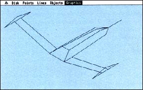 |
| Figure 1. The GFA Vector Display screen with a space ship displayed. This is just one of 10 objects on your START disk. Others include the space shuttle--and an animated bat! |
The program is started by double-clicking on the customized module. After the 3D routines in the module load, the GFA BASIC Interpreter or Run-Only Program loads automatically. Then the .BAS program is loaded and it controls loading of the object data (.DAT) file.
A Quick Demonstration
If you have set up your files and folders as described above, you are ready to run a demonstration of GFA Vector. Insert your work disk and double-click on the VECTOR.PRG icon to run the program. If you have a color monitor, you must be in medium resolution.
Now, go to the Disk menu and click on Demo program. You will see a complex demo that describes GFA Vector and then illustrates various features. Click the left mouse button to move to the next part of the demo and click the right button to end it. The space ship shown in Figure 1 is part of this demo.
Customizing a Module
To customize a module such as MODULE1.PRG to work with a program called TEST.BAS, you must first run GFA Vector. When the menu bar appears, select Create Module from the Disk menu. A dialog box will appear. If you are using the GFA BASIC interpreter, press the Delete key to delete GFABASRO.PRG and then type in GFABASIC.PRG and press Return. If you are using the run-only program, it is already entered as the default; simply press Return.
When you've pressed Return, the default name of the .BAS program will appear, MODUL.BAS. Press the Delete key to delete the default name and then type in your new program name. Then press Return again and the file selector box will appear. If you have set up GFA Vector with the folders described above, GFA Vector will first look in the MODULE folder for an uncustomized module program. Select MODULE1.PRG and then click on OK. GFA Vector will then customize MODULE1.PRG and re-write it back to the disk under the same name (you can later rename it to match the .BAS program, such as SPACE.PRG, so that you will know which modules you have customized).
Creating an Object Using Coordinates
If you have GFA Object (from the May 1989 START disk), you may create objects there, save them to disk and then convert them to GFA Vector .DAT format with the ANIMATOR.PRG included with GFA Object. GFA Vector also has an object creation facility, however.
When GFA Vector loads, you will see drop-down menus for Disk, Points, Lines, Objects and Graphics. GFA Vector lets you create objects two ways, either by entering numbers from the keyboard to define points and lines or by using the Graphics Editor to create them visually.
To have some data to work with, select Load file from the Disk menu and load DEMO.DAT from your work disk. Twenty-nine objects are included in this file, as detailed above.
The Point, Lines and Objects menus all have the same menus and their functions and uses are similar. On any of the three menus, list lets you list all or part of the list of points, lines or objects to the screen, while print lets you create a printed copy of the same list. The add function lets you add new points, lines or objects to the end of your list and the insert function lets you insert new point, lines or objects within the list. You can change any points, lines or objects or delete them with these functions.
The list, print and delete functions all use a similar dialog box. You may select a range using the (-) and (+) buttons. Left-clicking on one of the buttons changes the value by one; right-clicking on one of the buttons lets you move quickly through the range. Once you have defined the range, click on the OK box (or press Return) to list, print or delete the range.
The add function does not bring up a dialog box. Instead, it presents you with a data entry screen, since it adds to the end of the list. In order to add a point, you must specify the X, Y and Z locations for the new point separated by commas, such as: 0,90,0 [Return]. The permissible range for point locations is plus and minus 1023 in any direction. When you have completed entering point coordinates, simply press Return.
To add a line, you must specify the starting and ending points for the line by listing them according to their point numbers. For example, you may have added two points as points 0 and 1. To add a line between them, all you have to do is type in 0,1 in Lines/add. Again press Return when you have finished.
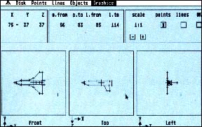 |
| Figure 2. GFA Vector's Edit screen in which you create and modify your objects. All three views of an object are available on a single screen and all functions are mouse- controlled. |
To add an object, you merely need to specify that it consists of points a through a through b and lines c through d, such as a,b,c,d.
The insert and change functions bring up a dialog box that lets you specify the point in the list you want to work on. Use the (-) and (+) buttons to move through the list, then click on OK to either insert a new line, point or object or change an existing one. GFA Vector will keep track of your previously defined objects, so that if you add a point or line in the middle of the list, the program will still define the rest of your objects properly.
Creating an Object Visually
If you select Graphics Editor from the Graphics menu, you will first see a diaIog box to select which object from your list you want to edit. Once you select one, you will see the editing screen shown in Figure 2. This is the screen in which you will create and edit your objects.
At the bottom of the editing screen are three windows showing the Front, Top and Left views of your object. The small window in the upper left shows the current location of the cursor, while the top right window lets you select the viewing scale (from 1:1 to 1:10) and lets you choose to edit points or lines. When you are finished editing an object, click on the OK box in this window. In the top center of the screen is an information window that tells you the range of points and lines used by this object.
To place a point, first make sure that there is an X in the points box, then simply move the cursor inside one of the view windows and left-click. A small cross will appear. To "lock" the cursor location in one window, so that you can set a point in all three dimensions, press and hold the right mouse button when you have the cursor where you want it in one window, then drag the cursor into another.
You can only connect lines between points that have already been placed. First, click in the lines box in the upper right portion of the screen, then select a point. Make sure that you have located it in all three dimensions using the right-hold/drag technique. When you have properly located the cursor over a point, you will see that the cursor cross hairs are open in the center in all three windows. Then, without moving the cursor, hold down the Shift key and click the left mouse button. You will hear a tone signifying that you have located the beginning point of a line. Then locate the ending point, again in all three dimensions, and then left-click when the cursor is over it. A second tone will sound and a line will appear between the points.
That's all there is to creating or editing an object visually. Practice using the right-hold/drag technique; it's pretty easy once you get the hang of it.
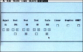 |
| Figure 3. The Display screen lets you set up automatic animation to see how an object will look in motion. Or you can choose a particular angle and size to check a particular view. |
Displaying a Graphics Object
The Graphics menu also has a Display object selection. If you click on this choice, you will be brought to the Display screen shown in Figure 3. From this screen, you may select the object to be displayed, the X-, Y- and Z-axis rotation of the object (Xrot, Yrot and Zrot), the magnification (scale from 1 to 511 with 64 being 1:1, or no magnification) and whether to show the object with XORed lines.
Under the rotation and scale choices are four boxes. Click in any or all of these boxes to vary that parameter during the display of the object. When this function is active, you will see an arrow in the boxes.
To Display an object, click in the Graphics box to the right of the screen. To leave the Display object screen, click in the ABORT box.
File Handling
Under the Disk menu, you have several choices. We've already covered the Create module and Demo program options above. The others are Load, Write and Delete file and Quit. Load file loads a .DAT object file into GFA Vector. Write file saves the current .DAT object file to disk. Delete file lets you delete a .DAT object file from disk. Quit takes you out of GFA Object and back to the Desktop; there is no confirming dialog box, so be sure that you have saved your objects before quitting!
Machine Language Routines and Arrays
GFA Vector expands the functions available in GFA BASIC by adding a number of machine language routines, invoked by the Call function in GFA BASIC. In order to perform smooth animation, GFA Vector sets up a second screen page in memory, draws on the second and then flips it onto the visible screen. GFA Vector uses one- and two-dimensional arrays to hold the various parameters.
The machine routines are:
- Init%--Deletes the second screen page and copies the first onto it. The routines Tfrm% and Linor% (see below) are then called automatically. Always call Init% before calling Vector%.
- Vector%--Uses the parameters in the arrays to draw a new picture. The old picture is deleted unless Ofrm% is called first.
- Linor%--If called, any background detail is deleted by the object.
- Linxor%--Causes the object to be drawn or redrawn so that the background is preserved.
- Ofrm%--If called before Vector% the old picture is not deleted.
- Tfrm%--When Vector% is called the old picture is deleted.
- Page1%--Puts the first screen page onto the monitor. Always end your program with one or the other screen pages on the monitor so that GFA BASIC messages can be seen.
- Page2%--Puts the second screen page on the monitor.
- Flip%--switches the screen page from page 1 to page 2 or vice versa, but has no effect if the screen has been selected by the Page1% or Page2% calls. Init% resets the page selection.
The arrays used by GFA Vector are:
- Obj%(N), where N is the object number. Permissible values are 0 for inactive and 1 for active objects.
- Col%(N), where N is the object number. Assigns a color to each object, 0-15 for low resolution, 0-3 for medium resolution and 0-1 for high resolution.
- Scale%(N), where N is the object number. Determines the size of the Objects. Permissible values are 1-511 with 64 being the object's actual size (1:1). Doubling this number doubles the size of an object.
- Pos%(N,0) specifies the X-position of the origin of object N. Permissible range is 0-639, for all resolutions.
- Pos%(N,1) specifies the Y-position of the origin of object N. Permissible range is 0-399 for all resolutions with 0 at the top edge of the picture.
- Rot%(N,r) sets the sequence of rotations for object N. The value of r is the sequence with permissible values of 0-2, 0 being the first rotation, 1 the second and 2 the third rotation. Permissible values of the expression are 1-3: 1 is the X-axis, 2 is the Y-axis and 3 is the Z-axis. For example, the expression Rot%(0,1)=3 means that the second rotation (r= 1) of object 0 is about the Z-axis (3).
- Xrot%(N) contains the integer values of rotation in degrees from 0-359 about the X-axis for object N. When viewed from the positive axis toward the origin, this rotation is always counter-clockwise.
- Yrot%(N) contains the integer values of rotation in degrees from 0-359 about the Y-axis for object N. When viewed from the positive axis toward the origin, this rotation is always counter-clockwise.
- Zrot%(N) contains the integer values of rotation in degrees from 0-359 about the Z-axis for object N. When viewed from the positive axis toward the origin, this rotation is always counter-clockwise.
- Endpunkt%(N,a) contains the X-position (a=0) and the Y-position (a=1) of the last point of object N. Permissible ranges are 0-639 and 0-399, respectively. After each Vector% call, the coordinates of an object N can be obtained from the Endpunkt% array. Then these values can be used as the position of object N and the object moved with just this single definition.
Getting the Manual
The original manual for GFA Vector is available by calling the Disk Desk at (800) 234-7001 or by writing to us at START. The price is $10.95, plus $3.50 for shipping and handling. Ask for Item Number TH002. Remember, the number of manuals is limited, so act fast!
Send your check or money order in the amount of $14.45 to: START GFA VECTOR Offer #TH002, 544 Second Street, San Francisco, CA 94107.
|