ICONOGRAPHICS
Creation!
Build Mountains with START's Fractal Landscape Generator
by Tom Hudson
START Contributing Editor
Now your ST can make mountains out of molehills--of data. Tom Hudson, ST graphics guru and author of Degas Elite and CAD-3D, has developed Creation! especially for the readers of START. Generate imaginary mountain ranges or use geologic survey data to reproduce real topography, then save your creation as a CAD-3D object or as a DEGAS or NEO image to give your art or animation that natural look.
Move mountains with CREATION.ARC is on your START disk.
How would you like to have your ST or Mega create realistic-looking landscapes with plains, mountain peaks and even oceans? What's more, what would you think if I told you that your computer could display real topographical data from the United States Geological Survey (USGS)? Well, with Creation!, you can do all this and generate and save color-coded topographic maps and create a 3D object file for use in CAD-3D. All this capability is merely a few mouse-clicks away when you use Creation! Let's see how it's done.
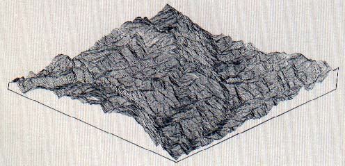
 |
| A random fractal landscape seen in perspec- tive view. |
PRESENT AT THE CREATION
You'll find all the necessary files in CREATION.ARC on your START disk. Copy CREATION.ARC and ARCX.TTP to a freshly formatted diskette and follow the Disk Instructions elsewhere in this issue to uncompress the files. In order for CREATION.PRG to run, CREATION.RSC must be in the same directory. CREATION.ARC also contains the customized Big Basin data file, called BIGBASIN.DAT, the source-code files and a program take-apart to help you understand Creation!'s operation.
Creation! must be run in low resolution mode on a color monitor. It will not run on a monochrome monitor or on a color monitor in medium resolution mode because the ST's 16 colors are required for the landscape altitude displays.
Let's run through a couple of sample sessions with Creation!. We'll learn the details later.
First, let's assume you want to generate a random fractal map and save a perspective view to disk, along with a CAD-3D file in moderate, or 40 X 40, resolution. Run Creation! and click on the "Random Fractal" selection on the GENERATE menu. After the landscape is generated, click on "Perspective" on the VIEW menu. If the map is satisfactory, you're ready to save it. Otherwise, you can keep generating new random maps until you have one you want.
To save the perspective view, click on "Save Perspective" on the FILE menu. When the file selector appears, type in the filename you want the picture saved under, including the .PI1 or.NEO extension. The image will be saved to disk.
To save the 3D file, click on "Save 3D File. " When the resolution selection dialog appears, click on "40X40". When the file selector appears, type in the filename you want to have the 3D file saved under, including the .3D extension. That's all there is to it!
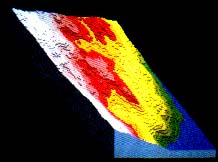
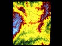 |
| Top view of the Big Basin in San Mateo County, California. |
Now, let's assume you want to use some real map data, such as the BIGBASIN data file, and save the top view, the perspective view and a 3D file in an 80-by-80 resolution. Run Creation! and select "Load Map Data" on the FILE menu. When the file selector appears, select the BIGBASIN.DAT file and the program will read the data into memory.
To generate a work map from this raw data, click on "Use Map Data File" on the GENERATE menu and select the "Full" button to use the entire map data file. The program will sample the map data and create the work map. Now generate top and perspective views by clicking on those selections on the VIEW menu. Save these views to disk by using the "Save Top View" and "Save Perspective" selection on the FILE menu. Remember to use .PI1 or .NEO extensions. Finally, save the 3D file by clicking on "Save 3D File" on the FILE menu, then selecting "80X80" and entering a filename with .3D extender for the 3D file. You're done!
I've found the Creation! program to be a great help in creating realistic, synthetic landscapes very quickly. I've sat in front of the computer for hours generating random mountains, valleys and bays just for fun. Its ability to use real-world landscape data, though, makes it a valuable tool for visualizing the actual terrain of our planet.
USING CREATION!--THE MENUS
When the program starts, you will see a familiar GEM menu bar across the top of the screen. There are four drop-down choices, DESK, FILE, GENERATE and VIEW.
On the DESK menu are your desk accessories and "About Creation!" which displays the program credits.
On the FILE menu, you'll find:
- "Load Map Data" allows you to load in a real-world map data file, available from Peerless Engineering Service (see sidebar). These data files contain sections of the earth's surface which have been mapped by the USGS or the Defense Mapping Agency for various uses. Map data loading can take some time, since standard files are commonly over 300K in size. In order to fit BIGBASIN.DAT on the START disk, I had to reduce the resolution of the Peerless/ USGS data file from its original file size of 352K, but Creation! will read either reduced resolution or full resolution Peerless format files. Once you have loaded the map data, you can use the GENERATE drop-down to create a map. "Save Top View" saves the top view of a previously-generated picture of a map to disk in either the DEGAS (.PI1) or the Neochrome (.NEO) format. You must include the .PI1 or .NEO extension in your filename to save the picture in that format. (Generate a top view from the VIEW menu before selecting this option.)
- "Save Perspective" saves the pseudo-perspective view of the map to disk in the same way as the "Save Top View" selection above. First generate a perspective view from the VIEW menu before selecting this option.
- "Save 3D File" saves the current map data to disk in CAD-3D's .3D file format. This file is loadable by either CAD-3D 1.0 or 2.0, and once loaded into CAD-3D, it can be viewed in true perspective with various coloring, lighting effects and camera angles. You have the option of creating your 3D file in one of three resolutions. The "80X80" option produces a map which is 80-by-80 vertices, for a total of 6400 vertices. This is a very fine resolution and takes a lot of memory and some time for CAD-3D to display. The "40X40" resolution is a bit more manageable, with only 1600 vertices, and the "20X20" resolution is smaller still, with only 400 vertices.
- "Quit" exits the Creation! program, returning you to the desktop.
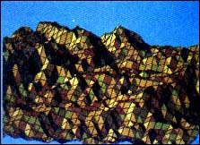 |
| The Big Basin in CAD-3D 40-by-40 resolution. |
A NEW GENERATION
From the GENERATE menu, you create your working map either as a fractal or from a data file.
- "Random Fractal" generates a truly random landscape using a technique known as fractals. You don't need the USGS map data files to create a fractal map. When you click on this option, a progress dialog is displayed which shows what the program is doing. There are eight processing phases in the creation of a fractal map, each one taking roughly twice as long as the previous phase. After all eight phases are complete, the program goes through a final processing phase, where the raw map data is converted into 3D data and color-coded 2D display data. When the fractal map is ready to view, the progress dialog disappears. You can then use the VIEW menu selections to look at your new landscape or use the FILE menu to save it to disk as a 3D object.
- "Use Map Data File" generates a map based on the data from a Peerless/USGS data file. You must load a map data file using the FILE menu before using this option, otherwise it is disabled. When you select this option, the program then allows you to choose which part of the map data to use for your map. If you want to use the full USGS data file for your map, click on the "Full" button or press Return.
If you want to "zoom in" on a smaller portion of the map data, use your mouse to select the portion of the map to display. Simply click in the large square box where you want one of the upper corners of the sample to appear and drag the mouse to the right--you will see a square "rubber box" appear. This is the area you will be using for your map. The rubber box is always square and its size is determined by its width, so just move the mouse left or right to adjust it. When it is the size you want, release the mouse button. Then click on the "Partial" button. (It's always a good idea to look first at the full view of a map before picking a smaller area to look at.)
Once you choose "Full" or "Partial", a two-stage progress dialog appears. The first stage is labeled "Sampling Map Data" and means that the program is stepping through the map data and sampling points according to your request. After this is done, the second stage, "Final Processing" is performed. This creates the color-coded work map and a 3D object database. You can now use the VIEW menu to look at the map or use the FILE menu to save the landscape as a 3D object.
A VIEW FROM ABOVE
The VIEW menu allows you to look at your map with color-coded altitude values. There are two viewing options:
- "Top" is a top view of the map, which is displayed as a multi-colored square in the center of the screen. The altitudes range from blue (water or altitude less than 0) to green (lowlands) to red (highlands) and white (mountaintops). To return to the main screen, click the left mouse button. After you have generated the top view, it may be saved to disk from the FILE menu.
- "Perspective" is a pseudo-perspective (isometric) view of the map, displayed in the same color coding as the top view. This view is more informative than the top view, as it allows you to see actual altitude changes in the map more easily. Once generated, this image can be saved to disk from the FILE menu.
FINAL NOTES
The Creation! program, while providing a quick, easy way to generate images of real and synthetic landscapes, could be improved. For example, I would like to see a fully user controlled landscape editor, which allows the placement of peaks, valleys, water areas, etc. by the user, with random fractalization of the remaining area. This is a rather complex piece of code and time and space did not permit such a feature in Creation!.
Another interesting observation came up while testing Creation! with real landscapes. Creation!'s fractal landscapes, while fairly realistic, differ from the real landscapes because the real maps have erosion features, such as valleys that have obviously been affected by water erosion. While highly math intensive, I'd like to see such an effect modeled by the ST. (Editor's note: If you would like to see an enhanced version of Creation!, let us know!)
I hope you enjoy Creation! as much as I do. It shows that with the right kind of information, such as the USGS data, the ST can perform every bit as well as more expensive machines.
Tom Hudson is a Contributing Editor of START and the creator of DEGAS, DEGAS Elite, CAD-3D, Cyber Control, Cyber VCR, Cyber Sculpt and The Antialiaser.
PRODUCTS MENTIONED
Cyber Studio (containing CAD-3D 2.0), $89.95. The Catalog, 544 Second Street, San Francisco, CA 94107, (800) 234-7001.
NEOChrome, $29.95. Atari Corp., 1196 Borregas Ave, P.O. Box 3427, Sunnyvale, CA 94088, (408) 745-2000.
DEGAS Elite, $39.95. Electronic Arts, 1820 Gateway Drive, San Mateo, CA 94404, (415) 571-7171.
|
|