T-SQUARE
COMPUTER-AIDED DRAFTING
by DAVE EDWARDS
Atari ST graphics aren't just for fun-they're also perfect for architects, engineers and drafters who need to create technical drawings for construction and manufacturing. With CADD-Computer-Aided Design and Drafting-you can design anything from a circuit board to a skyscraper. Here's the ST software that'll let you do it.
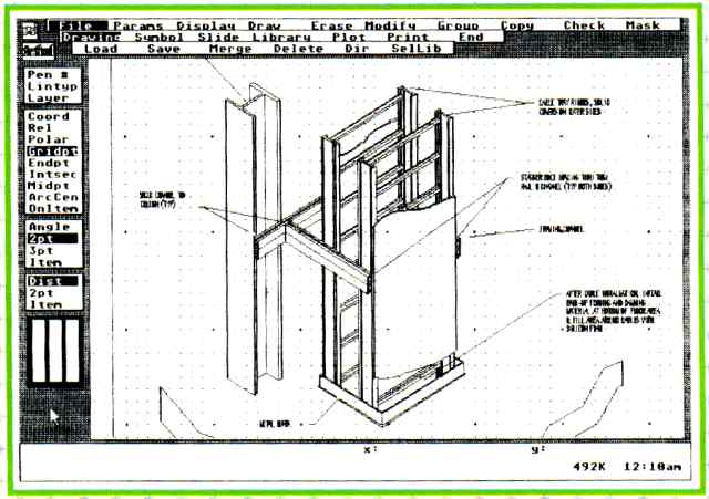
FIGURE 1: Drafix 1
Drafting is the process of creating drawings that represent real three-dimensional objects. These drawings are then used to build or manufacture the objects. Whether it's architectural plans for a skyscraper or the circuit design for a microchip, it can't be made until the plans are finished.
These drawings normally are produced to scale-larger or smaller than the objects they represent. Drawing plans to scale is often tedious, and making even simple changes can require a great deal of extra time; if a drawing needs to be changed to a different scale, a completely new drawing must be done.
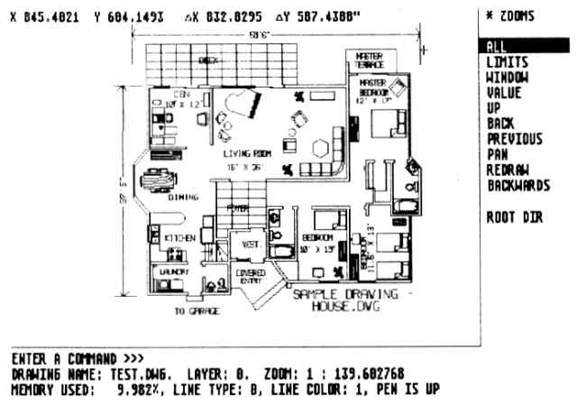
FIGURE 2 : First CADD
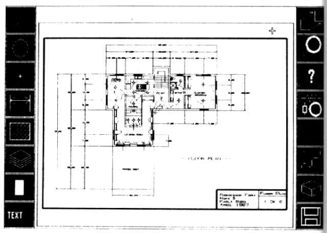
FIGURE 3: Athena II
"CADD" stands for "Computer Aided Design and Drafting." It's electronic drafting, and you can use it any time you would use ordinary drafting- for electrical design, architecture, structural engineering, etc. With a CADD program on your computer, you can create technical drawings, just as you would on a drafting table. But unlike drafting on paper, CADD makes it easy to change or rescale the drawing. And unlike an ordinary drawing or paint program, CADD works with individual objects or elements that can easily be moved around without disturbing any other elements in the drawing.
Like regular drafting, CADD uses the concept of layers. Suppose you're designing a building's plumbing and electrical systems. The pipes and wiring may be very close to each other- so close that, on a single drawing, it's hard to see which is water and which is watts. In regular drafting, the solution to draw the plumbing and electrical diagrams on two separate sheets of tracing paper.
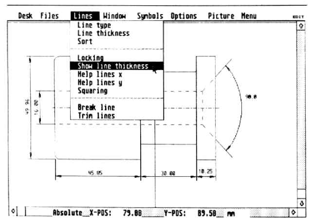
FIGURE 4: GFA Draft
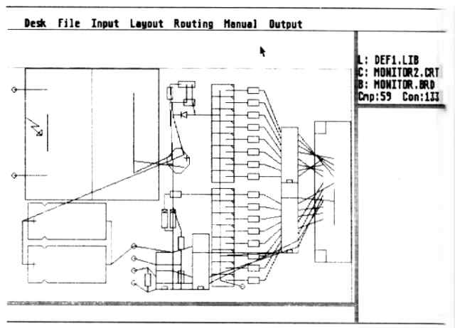
FIGURE 5: PC Board Designer's "rubberband" connections
With CADD, it can all be on a single "drawing," but on different layers of the drawing. Each layer can be made visible or invisible. When you're putting in the pipes, you can turn off the electrical level so the wiring can't be seen. When it's time to add wires, you can turn off the plumbing layer and turn on the electrical layer so the pipes won't get in your way. And when it's time to print things out, you can print a drawing that contains all levels, or just one or two.
Most CADD programs also include symbol libraries- components of drawings that you're likely to need often. Instead of drawing the same items over and over, you can usually draw your own objects, add them to the libraries, then pull them out again whenever you need them.
Best of all, with CADD you don't have to worry about getting it right the first time. If you place an object in the wrong place or size it wrong, you can change or delete it, and if a client wants a change in the design, you can make the change quickly and easily. That freedom can make for much greater design flexibility and creativity.
can't build a
microchip or a
skyscraper unless you
have finished plans.
CADD For The ST
In this article, we'll look at four CADD programs for the ST: Drafix
1, Athena II, First CADD and GFA Draft.
The chart compares the four programs' features. All four use the mouse for drawing and pointing on the screen, and all have similar commands for editing and adding objects to drawings. Each of these programs lets you use simple objects such as lines, circles and rectangles, but there are many different ways these objects may be placed and manipulated-and the more ways a CADD program offers, the better. And all these CADD programs let you print your drawings, usually with either a dot-matrix printer or a pen plotter.
The programs have one other thing in common: They all promise "new and improved" versions that should be available soon. Along with the current features, the chart also shows the features that are promised for the next release of each program.
Most of these programs are large and use as much memory as is available;
for CADD on an ST, the more memory the better. All the programs work on
both color and monochrome screens; I found the monochrome a little easier
to use because of the greater resolution, but color makes it easier to
keep track of different objects.
| PC BOARD DESIGNER
Some CADD programs are designed to perform a specific task, and PC Board Designer is one such program. It provides complete capabilities for designing electronic printed-circuit boards. The program allows you to use components from a symbol library and position them on a circuit board; then PC Board Designer automatically routes the electrical connections for you. This radically simplifies designing single- or double-sided PC boards for professionals or hobbyists. A library of components is supplied with the program. You select the ones you need and place them on the board in any fashion you wish, specifying the connections that need to be made-which pins to connect, how wide the connection should be, and whether 45- or 90-degree bends should be used. The program will then show you the connections you have made in straight-line or "rubber-band" form (see Figure 5). You can make any corrections or additions you need to the connections list; when the connections are all correct, the program's auto router will draw the connections for the final printed-circuit board (see Figure 6). The auto router is very flexible- you can specify X-Y direction and limit the length of a connection, and it lets you know if a connection can't be made. (If that happens, you can add wire jumpers, through-holes or blockades.) You can move components and reroute, sort the connections to improve routing efficiency or run the router manually. The component library includes most of the components you'll need; if you need one that's not supplied, there's a separate program included that lets you add components to the library. But printout is where PC Board Designer really shines - the program prints on Epson FX80-compatible printers, and options include pinhole plot for a drilling mask, component plan for silk-screening the component side, and actual printed-circuit layout. The program prints at double size, letting you reduce the printouts later for photoetching. PC Board Designer has one major drawback: The maximum board size is 6.3 x 3.95 inches, which severely limits what projects can be done with the system. I'd prefer to be able to design boards the size of the standard IBM PC board, which would cover most professional needs. That limitation aside, PC Board Designer is a great asset to anyone who designs printed-circuit boards.
CIRCLE 167 ON READER SERVICE CARD |
Drafix 1
Drafix 1 has been available for IBM PCs for quite some time as a low-cost
alternative to expensive programs like AutoCAD and VersaCAD. The experience
of Drafix's designers gives it a definite advantage over some of the other
programs - they've simply had more time to improve it than companies who
have just started writing CADD programs.
The Atari ST version of Drafix 1 is identical to the IBM version in almost every way. The IBM experience really shows in this program: it contains more drawing options than any of the others, and has features that even some of the higher-priced PC CADD programs don't have.
From Figure 1, you'll see that Draflx doesn't use GEM at all, but uses its own mouse-and-menu procedure. For ST veterans this can be annoying: You have to press a mouse button to see a menu instead of having it pop up by itself, but it's very easy to switch from one menu to another it's also easy to change the parameters for drawing, snap and angles-these change often, and it's very convenient to be able to change them without going to a menu.
Drafix can place double lines, which can really cut your work when you need lots of parallel lines. The program has 23 pointmarkers-small objects drafters use over and over for such things as line terminators. The 12 fonts help add variety to drawings. The options for dimensioning (defining the size of all or part of an object) and snapping (quickly connecting lines) are very complete Keyboard input for points in absolute, relative and polar modes is helpful for setting up designs using precise measurements. Drafix uses dimensioning parameters to aid in setting standards, so dimensioning and placement are precise and error-free.
The options for modifying elements impressed me the most; some, such as beveling (rounding off or creating angles on corners) and trim to edge (merging perpendicular lines), I have seen on no other CADD system. They're very powerful and could save a great deal of time. Two other strong points are manipulation by group or by fence. A group is a collection of elements that you flag individually, then manipulate all at once. A fence lets you manipulate elements within a given area.
Drafix supports pen plotters in a very advanced way. For multiple-pen plotters, you can specify which pen each object will be drawn with. Unfortunately, pen plotters are currently the only choice: though a dot-matrix printer driver is being readied for the ST, it's not currently available. For now, the plotter driver is very powerful, and you can do screen dumps to a dot-matrix printer or DEGAS-format picture file.
Draflx 1 comes with the most impressive set of manuals for a micro-based CADD system I have ever seen. There's an installation guide. a technical reference manual, and a tutorial manual that leads you step-by-step through the program's features.
This program is definitely geared for the professional user. At $195 it's twice the price of the other ST CADD programs, but it's also the most powerful CADD program I've seen for the ST and one of most powerful for any micro in this price range. The dot-matrix printer driver isn't finished yet, and I'd like a DXF (AutoCAD) translator; I also wish I could store plotter specifications, such as plot window and scale, in the drawing. Aside from these things, it's hard to find a flaw in this program.
First CADD
Once again, a best-selling CADD program for the 1BM PC has jumped to
the
ST. First CADD is designed to let you get a good feel for what CADD is
without spending a lot of money.
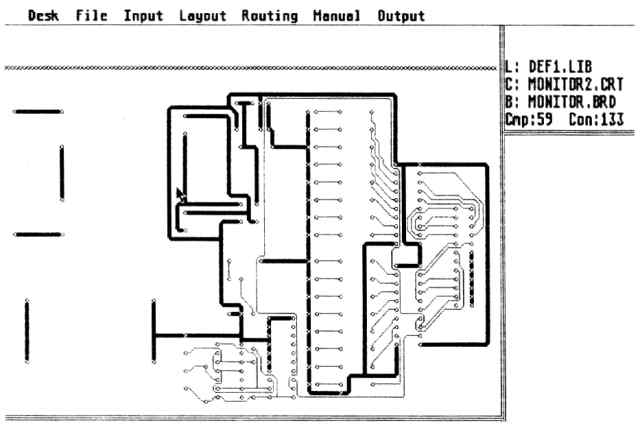
FIGURE 6: PC Board Designer's final connections
Like Drafix, First CADD uses its own multiple menu system (see Figure 2). To select a command you move the menu bar on the side of the screen, then press the right mouse button. Alternatively you can type a two-letter code for each command-a powerful technique once you've mastered the program.
First CADD has some nice features. such as the ability to create your own fonts. First CADD's publisher, Generic Software, offers symbol libraries for electrical components, flow charts and furnishings. You can add custom menus in conjunction with these furnishings, a feature that's found on none of the other systems. It really makes First CADD worth looking at.
First CADD can use files created with the IBM versions of First CADD and Generic CADD. The program prints on dot-matrix printers; a separate pen plotter driver is also available from Generic.
All in all, First CADD is a very straightforward system that's easy to learn; once you've mastered it, it lets you create drawings much faster than with some of the other systems. Generic Software will be offering a more advanced CADD program soon that will use First CADD files and symbols; if you own First CADD, you'll be able to upgrade to the new program using a rebate system.
of the most
important elements
of a CADD system
is its user interface.
Athena II
Athena It is an icon-based system with more features than any ST CADD
program except Drafix 1. You choose commands by selecting one of the icons
at the side of the drawing area (see Figure 3); in most cases, another
set of icons then appears, increasing the options available to you.
The icon interface makes Athena II very quick to learn-in fact, 1 was able to go through most of the functions without ever opening the manual. The manual itself is very thorough and explains every command in sufficient detail. It also has thumb indexes printed on the pages. making it easy to find a particular section.
Athena has most of the features you'll need to create drawings. An especially nice feature is semi-automatic isometric creation and pattern fill of areas- not just hatching (slanted shading lines). Also helpful is the ability to display circle center lines. A good set of architectural symbols is available from Iliad. The program does plot high-resolution prints on a dot-matrix printer; however, it uses GDOS, and currently has no plotter drivers (they'll be available with a later version of the program). You can also dump the screen image as a DEGAS file.
Some of the most exciting Athena features are still on the drawing board. A command language interface will soon be available so that custom applications for the program can be written. Iliad is also working on the DX translators that will let you use files from AutoCAD; since most IBM CADD packages have DXF translators, this will make Athena II compatible with a majority of CADD systems. An engineer using an ST could exchange flies with an architect working on a project even if the architect were using one of the popular IBM packages. Iliad's DX translator is almost finished and should be available soon.
As it is, Athena II is a useful program; when some of the promised enhancements become available, it will have even greater potential. And Iliad is working on another CADD program aimed more at high-end users, which should be available soon.
GFA Draft
GFA Draft is the only one of these CADD packages that uses GEM dropdown
menus and slide bars. You choose commands by making selections from the
menus and you can move around your drawing by using the slide bars (see
Figure 4).
GFA Draft was created by GFA Systemtechnik in Germany, the same company that brought you GFA BASIC. Its European origins show up in the fact that GFA Draft tends to work better in meters and millimeters than in inches, and it doesn't use feet at all. It's understandable, and for some kinds of drafting it doesn't matter; but for American architects and engineers, it needs to work in feet and inches.
The program comes with a standard array of commands, but it has few editing features other than delete. However, GFA Draft has more commands for manipulating areas of a drawing than any other ST CADD program. The fence command lets you place a box (or "fence") around an area of your drawing; you can then perform manipulations that only affect the objects that are inside the fenced area. Some of the more unique commands using a fence are the stretch/compress and skew commands. Few CADD systems have these, and they can come in very handy when you need to change the shape of a particular area of a drawing.
GFA Draft also comes with several symbol libraries, including symbols for architectural drawings, electrical layouts and flowcharts. These libraries are one of the nicest features about this program, and can help you get an early start on your drawings.
The program does produce excellent printouts on dot-matrix printers, and also supports some pen plotters. However, I would really like more commands in GFA Draft, especially commands for editing objects. MichTron, the American distributor for GFA software, will soon be releasing GFA Draft Plus; it may have some features I'd like to see.
The Best Choice
One of the most important elements of a CADD system is its user interface.
I didn't find it odd at all that every CADD program I review here uses
a completely different approach to how commands are chosen and used; though
they all use the ST's mouse, only one actually uses a full GEM interface.
With these differences, it's especially important for you to try these programs before you decide to buy one. Find a software dealer who will let you try out each program, and evaluate how well it seems to suit your needs. You'll find that every program has features the others don't, and that each one does some things better than the others.
Choosing a CADD program is very much like choosing a car; you must balance the features you want with the price, and make sure that it feels comfortable to drive. All four of these programs offer good performance for the price, but only you can decide which one most closely matches your needs.
If you'd like more articles like this, circle 169 on the Reader Service Card.
Dave Edwards has worked with microcomputers for more than 15 years, and is currently the CADD Manager for Tiller/Butner/Rosa, Architects, in Montgomery Alabama.
Atari ST CADD Comparison Chart
CIRCLE 163 ON READER SERVICE CARD
CIRCLE 164 ON READER SERVICE CARD
CIRCLE 165 ON READER SERVICE CARD
CIRCLE 166 ON READER SERVICE CARD
Version reviewed
Price
Number of layers
Lines
single
Double
Tangent
Perpendicular
Parallel
Offset2
At angle from other
Number of line types
Variable line widths
Arcs/Circles
3 point arc
4 point arc
2 point, angle arc
Center, radious arc
Center, radious circle
2 point circle
3 point circle
Parallel arc/circle
Offset arc/circle
Center lines
Shapes
Rectangles
Polygons
3 point elipses
Elliptical arcs
Chain shape3
Freehand sketch
Spline curves
Points/Pointmarkers
Number of Types
Text
At selected angle
Text height
Selectable justification
Number of fonts
User-definable fonts
Symbols
Symbols libraries support
Scaled
Rotated
Remove all
Atari ST CADD Comparison Chart continued
Dimension
Angular
Horizontal
Vertical
Parallel
Rotated
Chain
Baseline
Radius
Diameter
Coordinate
Leader
Centerline
Hatching/Fills
Number of paterns
Select angle
Select spacing
Isometric Creation
Keyboard input
Absolute
Relative
Polar
Snap Modes
Gridpoint
Endpoint
Intersection
Midpoint
Centers
On item
Tangent
Parameter Selections
Layers
Project information
Units
Scale
Sheet orgin
Sheet size
Sheet margins
Grid orgin select
Grid aspect select
Grid highlight spacing
Grid dot spacing
Dimension lengths
Dimension terminator type
Dimention text height
Dimention text angle
Dimension text locations
Background color
Grid color
Atari ST CADD Comparison Chart continued
Menu colors
Prompt colors
Display
Redraw
Zoom in/out
Zoom area
Pan
Show last
Save view
Recall view
Full screen
Extent
View actual size
Grids on/off
Text on/off
Circle center lines on/off
Menu on/off
Modify
Move
Copy
Rotate
Mirror
Layer
Pen
Linetype
Font
Text size
Stretch
Break
Channel
Edge
Divide
Corner
Fillet
Bevel
Symbol explode8
Symbol replace
Shape close
Shape fill
Shape smooth
Shape explode8
Group
Item
Fence
Path
Save as symbol
Delete
Modify
Copy/move
Mask
Atari ST CADD Comparison Chart continued
Fences
Copy/move
Delete
Mirror
Rotate
Scale
Mask9
Modify
Stretch/compress
Skew
Inquire
Area
Angle
Distance
Item
Print object report
Symbol
Symbol list
Mask9
Layer
Item
Merge Drawings
Save Screen Image File
Plotting
Hardware options
Text fill
Polygon fill
Pen select
Best fit
Scale
Support pen plotters
High-res dot matrix
Command Language Interface
Function Key Macros
DFX Translator 10
IGES Translator 11
P: Proposed for later release
Notes:
1 Only 10 layers displayed ar one time
2 Offset lines are parallel at a selected distance
3 Combines selected objects into one shape
4 Increments of 90 degrees
5 Area fill patterns
6 Done by placing active points; regular snap proposed for
later release
7 Display entire drawing on screen
8 Exploding an object breaks it into its basic components
so that they can be manipulated separately
9 Masking prevents objects or layers from displaying
10 DXF is the file exchange format used by most IBM PC CADD
systems
11 IGES is the file exchange format used by most mainframe
CADD systems