BEHIND THE BIT PLANES
FIND OUT HOW
by Xanth Park
FujiBoink!, the bouncing rainbow fuji, is the best graphics demo START has seen on the Atari ST We have received many requests from people wanting to know just how it was done. So, we went to the source: the programming wizards at XANTH. After a little arm twisting, they agreed to relinquish their secrets. All related programs, plus source code, may be found in the FUJI.STQ folder on your START disk. Please note: FujiBoink! requires a color monitor.
In the beginning, there were bouncing balls. Lots of bouncing balls: Amiga, Atari 8-bit, and Atari ST. Then there was FujiBoink!, which demonstrated the superiority of Atari 8-bit graphics. Now, FujiBoink! has been ported to the ST. This is the tale of that heroic feat.
(Editor's note: Amiga introduced its graphics power with a demonstration featuring a rotating bouncing ball. In November, 1986, Atari showed up at COMDEX, in Las Vegas, demonstrating the same bouncing ball on both the ST and the Atari 8-bit machines. The 8-bit version was done by XANTH, a Seattle computer center. A few weeks later, at CES, XANTH was demonstrating a rotating, bouncing fuji (the Atari trademark symbol) with scrolling rainbow on the 8-bit Atari's. Inevitably, this same demo was adapted, with startling results, on the Atari ST.)
A while ago, a fellow and I were discussing the Amiga and its bouncing ball. He said he was impressed by the large number of rotation calculations that the Amiga was doing in real-time. I hated to disillusion him, but I had to set him straight: The spinning is just an illusion. Now, I don't know what people think FujiBoink! is doing, but again, it's all a trick. If you're expecting some sort of miraculously fast 3D rotation and polygon-filling routines, do not read further-and give my regards to the Easter Bunny.
But before we ruin the illusion by explaining how the magic works, those of you who have not seen FujiBoink! should read the sidebar and get the program up and running.
XANTH TELLS ALL
The Effect: A red-and-white checkerboard pattern is displayed. A translucent title square fades in over the checkerboard. The Atari fuji symbol appears, a rainbow of colors cascading down its face. It casts a transparent shadow on the background. The title square fades out. The fuji falls and bounces and spins all over the screen at 60 frames per second.
How It's Done: FujiBoink! sets the screen to low-resolution and calls VDI to draw some red squares on a white background. It reads part of FUJIBOIN.D8A (d-eight-a: data, get it?) and stuffs it into screen memory for the title screen, which is actually a portion of a NEO picture. The light pink squares of the title square create an illusion of translucency, which is heightened by the fade-in and fade-out, accomplished by adjusting the color registers.
The rest of FUJIBOIN.D8A is read in. Most of this data consists of 32 predrawn views of the fuji in varying stages of rotation, and the rest is shading data for the side of the fuji. Successive views are moved into screen memory at the appropriate place and time, thus creating the illusion of rotation and movement. The transparent shadow is the result of careful manipulation of bit-planes and color registers. The rainbow is generated by a raster-interrupt routine.
GENERATING THE FUJI VIEWS
Well the secret is out: FujiBoink! is just a glorified cartoon. Does this mean youll stop reading?
Thought not. I will now attempt to explain how the 32 views of the fuji are generated by the FUJIDRAW program.
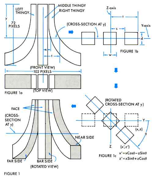
The fuji symbol has three basic parts, which I call the left thingy, the right thingy, and the middle thingy (see Figure la). At any value of Y, the fuji's cross-section can be described by the middle thingy's width, W; the fuji's thickness, D; and S and T, which define the contours of the left and right thingies (see Figure 1b). The values for S and T were chosen manually, although a mathematical description is certainly conceivable.
To create the data file, a rotation operation is performed on each point of the cross-section and the face, farside, barside and nearside are plotted on the screen (see Figure 1c). Then, for the shadow, each thingy-section is projected mathematically against a backdrop, assuming a light source 11.25 degrees to the side and 10 degrees above the horizon.
This basic process is repeated for every value of Y and every rotation. Each view, as it is completed, is written out to disk. Actually, only bit-planes 1 to 3 are saved, for reasons soon to be revealed.
One other point: Each view is offset horizontally from the preceding view so that no run-time shifting is required to move the fuji horizontally. As you can see, FujiBoink! proper hardly does any work.
TRANSPARENT SHADOWS AND DISPLAY STRUCTURE
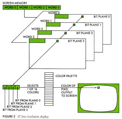
The ST uses a bit plane display structure. In low resolution, four 320-by-200 bit-planes are used (see Figure 2). The principle behind the transparent shadow is this: draw the background grid on plane 0, do all animation in planes 1 to 3 (leaving plane 0 alone), and with the proper color register assignment, voila! Transparent shadow.
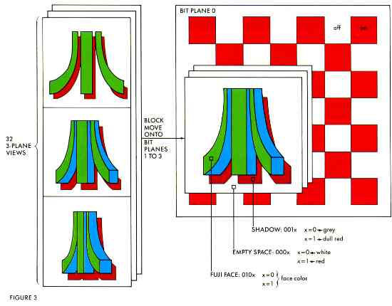
Perhaps an example will help to elucidate matters (see Figure 3). In this particular case, the shadow of the fuji is represented by pixel 001x binary. What's with the "x"? Well, the shadow is drawn as 0010 pixels, but only the three most significant bits are saved; the least significant bit effectively merges with plane 0, the grid. This way, the color of the shadow will depend upon what it overwrites. The fuji's face is pixel 010x, and empty space around the fuji is 000x.
Now, if at a particular point the grid is 0 (white), the situation will be empty space (0000), shadow (0010), and face (0100). Therefore, color register 0 should be white, register 2 should be grey, and register 4 should be whatever color the fuji's face is supposed to be. If, however, the grid is 1 (red), the empty space pixel will be 0001, shadow will be 0011, and face will be 0101. Color register 1 should be red, register 3 should be a dull red, and register 5 should be the same as register 4, because the color of the fuji's face does not depend on the grid. On the other hand, the colors of empty space and the shadow do depend on the grid, and by using bit-plane 0 to select appropriate color registers, the transparency effect is easily produced.
OVER THE RAINBOW
The rainbow effect which is so easy on the 8-bit Atari's, posed two major problems on the ST: how to change the fuji's color on the fly, and what to change it to.
The first problem was solved in Tom Hudson's ST Color Palette article (ANALOG magazine, January, 1986). The technique consists of programming the 68901 Multi-Function Peripheral chip to generate an interrupt every scan line. The interrupt service routine can then stuff new color values into the color registers. This is not the way Atari recommends doing this. Their method uses the built-in HBLANK (Horizontal Blank) interrupt. Unfortunately, I was unable to get that method to work, so I left well enough alone, and went to bed.
The second problem was an esthetic one. When the ST's 512 colors are laid out in RGB order (blue varying most rapidly), the rainbow does not really look so hot. The order I finally settled on is generated thusly (in pseudo-pseudo-code):
i=0
 for red=0 to 7
  for blue=0 to 7
   for green=0 to 7
    rainbow( i )=((red*3) mod 8)* 256
                 +green* 16
                 +blue
    i=i+1
   next
  next
 next
The red component is multiplied by three to provide a little more variety in the rainbow.
CALCULATING SHADING
This is embarrassing. This part of the project took nearly four days, mostly because of my own stupidity. (Sample mental process to convert 90 degrees to radians: Well, 90 degrees is one-quarter of a circle, so in radians that's one-quarter pi, right? AAAARRRGH!) This was also the time I discovered that Alcyon C wouldn't let me initialize a float array, and that the arc-tangent function atan() wouldn't link. More AAAARRRGH!
The idea was to generate realistic coloring on the side of the fuji, for each scan line of each view, according to the following formula:
brightness=d*cos( i )+s*cos( a )n
where:
d is strength of diffuse reflection (70%)
i is angle between light source and surface normal
s is strength of specular reflection (30%)
a is angle between reflected light and sight vector
n is 5
I didn't make all that up. I got it out of a book (see Refrrence).
Each brightness value is mapped onto an ST color, starting from dark blue at the low end, through light blue to white at the high end. The interrupt routine described above also stuffs the fuji side-color registers.
THOSE GREAT SOUND EFFECTS
I know, I know, there's only one sound effect, and yes, I agree, it's not so great. Maybe next time.
ETCETERA
FujiBoink! is written mostly in C. The 3-plane block move and clear routines and the interrupt service routines are written in assembly language. Those who wish a detailed, technical explanation of the coding are invited to dissect the source code on the START disk.
(Editor's note: START is interested in seeing any variations on FujiBoink! that readers come up with. How about a custom data generator?)
REFERENCE:
- Procedural Elements for Computer Graphics by David F Rogers, Osborne/McGraw-Hill, Berkeley, CA.
CREATING AND RUNNING
FUJIBOINK!
FujiBoink! requires a data file over 118K in size; which is far too large for the START disk. The FUJI.STQ folder holds three programs that create separate portions of the data and a fourth program that binds them into the final data file. The following instructions will get your fuji up and boinking.
1 Open the FUJI.STQ folder on your START dish and copy the following files to a blank, formatted disk.
FUJIDRAW.PRG
FUJISHAD.PRG
GETTITLE.PRG
PEND.PRG
TITLE.NEO
FUJIBO1N.PRG
2 IMPORTANT! Set your ST'S resolution to Low. Some of the data creation programs actual screen grabs.
3 From the disk you just moved the six files to double-click and run FUJIDRAW.PRG. This program will create a series of fuji's on the screen and write them to a data file called FUJIDRAW.D8A. The whole process will take about seven minutes.
4 Now, run FUJISHAD.PRG, which will create a data file called FUJISHAD.D8A
5 Next, run GETTITLE.PRG. This will display the T1TLE.NEO picture and capture a portion of it to a file called TITLE.D8A.
6 Click and run PEND.PRG. It will bind the other three data files into one 118K file called FUJIBOIN.D8A. Once you have your final FUJIBOIN.D8A FILE, you may delete the other three .D8A files. (PEND.PRG will display a couple of bombs before returning to the Desktop. Try to pretend this didn't happen. It won't affect the final result.)
7 Copy FUJIBOIN.PRG to the same disk as FUJIBOIN.D8A. These are the only two files you need to run FUJIBOINK.
8 You're done! Click and run FUJIBOIN.PRG to see the demo. While running, you may press any function key to freeze or restart the bouncing fuji. Press the Space bar to return to the Desktop.