Monochrome-Gray
HIGH RESOLUTION ONLY
Part II
by Charles Bachand
Charles Bachand, when not tooling around town in his 300ZX, can usually be found racing R/C cars or busily managing his own area on DELPHI, the Hobby SIG. His username is, appropriately, BACHAND.
Apples to Oranges
You've probably all seen an interesting piece of ST software called the ST Xformer. This program allows you to run Atari 8-bit programs, those destined from birth to run only on Atari XL's and XE's and their older cousins, the 400 and 800, on your ST computer. It uses software to make your 68000-based computer think it houses a 6502 processor. It does this not without some sacrifices, though.
The biggest toll is that in execution speed—the Xformer acts like an Atari 8-bit computer that is operating on less than half its cylinders. The job gets done, but the time it takes to do it is over twice that normally needed by a real 8-bit computer.
The slow speed of the ST Xformer can be attributed to the process of conversion. In this case, the software must look at every byte of the 8-bit program and ask itself, "What would I do with this if I were an 8-bit computer?" There are a lot of "what ifs" to consider, and all this pondering takes time—a lot of it. Who ever said that turning apples into oranges was easy?
We will be doing a not too dissimilar job of conversion this month when we display low-resolution DEGAS pictures using the Mono-Gray routines that were presented in our first installment.
Bit-planes, trains and automobiles
The internal makeup of an ST's monochrome screen area is quite simple. First you start with a 32,000-byte area of RAM. This memory, because of hardware constraints put on it by the graphics processor chip, must start on a page boundary (its starting address must be a multiple of 256). Each line that is displayed on the screen is made up of 80 of the total 32,000 bytes, while each bit of those 80 bytes represents one of the 640 pixels on the line. It's just simple math: eight bits per byte times 80 bytes per line times 400 scan lines equals 256,000 bits or 32,000 bytes of RAM.
With a monochrome monitor hooked up, the graphics processor chip reads and displays this 32K block of memory 70 times each and every second. It's quite simple and easy to understand. Too bad the same can't be said when working with color.
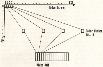
Graphics chips, and the way that data must be stored in RAM in order to work with them, are a strange lot. They were designed to show off a program's text/graphics in the shortest time possible (it's not nice to hog a computer's memory—it has other things to do). Because of this, it's not always intuitive just how graphics data is stored. Just take a look at Figures 1 and 2, and you'll see where the apples and oranges come in.
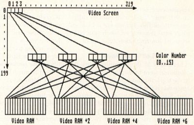
Figure 1 shows the relationship between what you see on a monochrome screen and what is found in video RAM. As you can see, there is a one-to-one correspondence between the two. Figure 2 on the other hand, is an entirely different kettle of fish. Let me see if I can explain what is going on when your ST is set to its low-resolution color mode.
Let's pretend
Let's start at the beginning. You, the computer, want to display the first pixel in the top left-hand corner of the screen. Since this is the 16-color mode, we'll need four bits of information. The obvious method (that of using the first four bits in the first byte of video RAM) is, unfortunately, not the correct one. We instead must take the first bit from each of the first four words, combine them (in reverse order) before we finally get the color number. This four-bit number is an index into our array of 16 colors used to select the proper values of red, green and blue to paint at that point on the screen.
The process is repeated for the second pixel, this time using the second bits from the first four words. We continue this way until we've exhausted these (only 16 bits in a word, remember) and start all over, this time using the second set of four words. If this method of accessing the data in the screen RAM looks awkward to you, just remember that you normally have no need to handle it in this method. It is, however, the most efficient way to do it—if you're a graphics processor chip.
Fade to gray
Now let's assume that you are color-blind. You look at a color monitor, and you see but a black and white picture. You can tell the difference between two colors only if their brightnesses are different. We normally assign a value between 0 and 7 for the brightness of each of the three color guns in the picture tube. Being color-blind (remember), your mind adds these three color values together to produce a gray scale where the brightness values range from 0 to 21.
Now with all these possible brightness values to work with, you might think we should initialize the Mono-Gray routines with a value of 21, like so:
@ginit(21)
This is the ideal condition, able to handle every possible brightness level; but because twenty-one 32K screens consume 672K of RAM, most people will run out of memory before all the Mono-Gray screens are established.
There is also our old friend, "Mr. Flicker," to contend with. Cycling through 21 different screens takes 3/10 of a second, allowing you to display only 3⅓ Mono-Gray screens each second. While the GFA BASIC code is optimized to reduce this flicker for colors near the middle of the gray scale, those near the ends will most likely give you a headache. No, we'd better leave trying to show 21 different shades for when we have a camera set up to do time-lapse photography.
We'd be much better off initializing for seven Mono-Gray screens and scaling down the brightness values to match our new limits of 0 to 7. Now we're dealing with only ⅓ the amount of RAM as before (now 224K), and our display rate has increased from three to ten frames per second.
Listing 1 (see DEGAS__1.GFA on disk versions of ST-LOG, as well as on DELPHI) displays low-resolution DEGAS pictures using this method. Merge it in to your Mono-Gray routines that were coded in GFA BASIC from last month at the place where you normally put your own code, then run it.
Yet another Mono-Gray routine
I should tell you at this point that I've added one more routine to the Mono-Gray code. Procedure gframe(num&) will allow you to view any of the Mono-Gray drawing frames individually simply by substituting a frame number for the parameter. The frame number must be an integer value in the range of [1..gmax&] where gmax& is the total number of frames. The code is comprised of only three lines, so I'm including it here:
PROCEDURE gframe(num&)
  VOID XBIOS (5, L : -1, L : gptr% (num&), -1)
RETURN
This code will allow us to easily return to viewing a Mono-Gray drawing screen after calling up a file selector box in order to load a picture file.
Seeing as how this application is being done entirely in GFA BASIC, I should warn you that the code runs a little on the slow side. GFA BASIC 3.0 happens to be one of the fastest BASICs around, but it is an interpreted (noncompiling) BASIC and so, just like ST Xformer, it has to identify and interpret each and every line of BASIC code it comes across. This, unfortunately, takes time. It's going to take time to draw your picture. How much, you ask? Really, not very long—only about 30 minutes.
30 minutes!
"What? Thirty minutes? This guy must be nuts!" you're all saying just about now. After all, it only takes Mono-Gray a split second to draw a gray square that nearly fills the entire screen. Well, the main reason for the snail's pace is that we're not using the ST's drawing routines efficiently. What we are doing is analogous to painting the side of a barn with a Q-Tip swab.
Let me try to illustrate what I mean. If we were to REM out the @gbox() statement (the one that calls the Mono-Gray code that actually does the drawing to the screen) the program would take only two minutes and 40 seconds to run. Why? Well, we happen to be calling a very sophisticated routine through the Mono-Gray code, the GFA BASIC statement, BOX.
The use of the BOX statement was the easiest to implement from our point of view because we happen to be drawing boxes on the screen. Unfortunately, these happen to be very small boxes (2 × 2 pixels). We also happen to be drawing 64,000 of these boxes for each of the seven Mono-Gray screens. That's a total of 448,000 squares to produce one seven-level gray scale picture!
When we use the Mono-Gray code directly to draw a large gray box that almost fills the screen via the @gbox() procedure, we are actually making only seven graphics calls (one for each of the Mono-Gray screens) and not 448,000 of them as is the case for DEGAS pictures. I trust that you now see why the program tends to slow down a bit.
To draw, or not to draw
The replacement @convert procedure in Listing 2 (see DEGAS__2.GFA) will accomplish the very same thing as that found in Listing 1, but with a substantial savings in speed. Given the task of displaying an entirely white screen in seven level gray scale, we trim our time down to 26.25 minutes—a savings of 3.75 minutes.
We gained these extra few minutes by switching to the use of the Line-A routine PSET that is callable from within GFA BASIC. PSET allows you to plot individual points with increased speed, but it will not draw boxes—or anything else for that matter. In order to draw our 2 × 2 boxes, we need to call PSET four times—once for each corner.
Since I didn't want to mutilate the original Mono-Gray code in the process, the Line-A routines (as well as the frame switching code found in last month's Mono-Gray procedure, @gcode) was substituted for the original call to @gbox(). This routine no longer wastes time passing parameters to a second procedure—it is now all in line code.
Incidentally, the time of 26.25 minutes we got when drawing a totally white screen happens to be this new code's "worst case" scenario, since displaying a completely black screen requires only 3.4 minutes. Why the big difference? The secret is not in what is being drawn, but rather in what is not. This new code assumes that a call to the routine @gcls was made before drawing began, thus filling all the Mono-Gray drawing screen with zeros. The initial setup call to @ginit() also erases these screens, so we don't have to worry about erasing for the first picture.
Now, since all the possible pixel positions are in their off state, we need only to draw those that need to be turned back on. In using this method, some DEGAS pictures will take longer to draw than others. On the average, your DEGAS files will require only about 15 minutes of drawing time in order to be displayed.
We no need no stinkin' graphics calls!
Remember earlier when we discovered how fast things sped up when we REMed out all calls to the graphics calls? It then took us only two minutes and 40 seconds to process a picture file. I didn't say "display a picture file," for unfortunately, nothing was drawn to the screen. Well, our final rendition of the program doesn't call these graphics routines either, but still manages to generate viewable data. How? By writing directly to the screen RAM via the use of POKE statements. By doing it this way, we avoid all the unnecessary code and error checking that software designed to handle three different graphics modes must contain.
Listing 3 (see DEGAS__3.GFA) takes only 3.75 minutes to generate a completely black screen. This is comparable to the 3.4 minutes taken up by Listing 2 to perform the same feat. Handling a totally white screen (and anything in between) is where the code in Listing 3 really shines. Listing 2 took 26.25 minutes to do this—Listing 3 does it in 7.5!
To do this, we need to do all the masking, shifting and poking to screen memory ourselves. One might think that since it is being done in BASIC that it would be actually slower than if the operating system were handling the graphics. But our particular application actually runs faster in BASIC.
The main trick is in the substitution of the following line of GfA BASIC code for the call to @gbox() in Listing 1 or the four calls to the Line-A routine PSET in Listing 2:
videoX(index&) = OR(videoX(index&), SHR(&HC0000000, i& + i&))
This line of code does basically what the graphics calls before it had done, but it does them to an array of seven long-word variables called video%(). It builds up the 32-bit wide values by ORing them with a two-bit wide mask (&HC0000000) that gets shifted two bits to the right for each pixel. We're using two-bit masks and two-bit shifts because we want to plot two pixels in width for each pixel in the color DEGAS picture. The actual plotting is being done by the following code:
FOR index & = 1 TO gmax&
  LPOKE gptr%(index&) + offset&, video% (index&)
  LPOKE gptr%(index&) + offset& + 80, video%(index&)
NEXT index&
Now since we also want to double up the pixels in the vertical direction to properly display a 200-line picture on a 400-line display, we need to include the second LPOKE statement with the value of 80 added to the screen offset. Since there are 80 bytes of data on each scan line, this will display our second longword right under the first. We now need to position the offset value four bytes further along the display with:
ADD offset&, 4
Now we need a way to skip over all the odd-numbered scan lines (odd if numbered from 0.399) so that the first LPOKE will not wipe out data left by a previous use of the second LPOKE. That's where the use of the following IF statement comes in handy:
IF MOD(offset&,80) = 0
  ADD offset&, 80
ENDIF
This says that if the new offset value we got after adding 4 to it is evenly divisible by 80 (which is the case at the beginning of each scan line), then add 80 more bytes to it so that it points to the beginning of the next scan line.
Well, that's all the room we have for Mono-Gray in this issue. Next time we'll learn how to display art that has been compressed into the Tiny format, and we'll see if we can speed up things still further using machine language subroutines. Until then, may your blue skies be gray.