Monochrome-Gray
by Charles Bachand
HIGH RESOLUTION ONLY
I do most of my writing in monochrome—the act of writing doesn't usually require color. The smaller dot size of the SM124 monitor, along with its 400 scan lines (twice as many as a color monitor) and its better-looking character set does wonders for the eyes. I have to wear glasses as it is (due, I suspect, from staring at color monitors all day), so whenever I get a chance, I work in monochrome.
There are things to be said for color monitors. Their appeal lies, of course, in "color." You just can't get the full range of the spectrum out of a monochrome picture tube—that should be as plain to everyone as black and white. That is why I, like a lot of ST owners, have two monitors. We end up doing a lot of plug pulling or switch flipping during our sessions in front of the ST's keyboard, but we are generally, for the most part, a happy lot.
Now, had I started out on a somewhat limited budget that required me to purchase one and only one monitor, I would have gone with monochrome. I am, deep down, somewhat of a tightwad, and the last time I checked, color monitors were much more expensive than my personal favorite. Yes, a monochrome monitor was and is the way to go for me and many like me. But there is something missing.
A color monitor, being an analog device, is capable of displaying a wide range of colors, as well eight levels of brightness for each of the three colors (red, green and blue) that are used make up what we see on the screen. A monochrome monitor is pretty much the opposite, using digital signals instead of analog ones. You must all be familiar with "digital" by now. Those ones and zeros that run your computer are also responsible for turning the pixels on your monochrome screen on and off. Force a bit on (a "I" condition) and a dot lights on the screen. Shut off a bit ("0" condition) and a pixel is extinguished. Ones and zeros and that's basically it. So, with only two possible states, there is no way to produce any shades of gray. Either a pixel is white, or it's black. There is no middle ground to tread. Or is there?
The Pixel Gazette
The Sunday newspaper—how often have you looked at it? For those who manage to make it past the comic section, there are usually quite a few articles with photos associated with them. Photos of escaped criminals, of people running for office, of children with dripping ice cream cones, of cute and cuddly puppies. If you take a good look at these black-and-white photos with the help of a magnifying glass, you'll see that they're made up of tiny dots. They almost remind us of pixels, don't they? In fact, they are pixels not dissimilar to those on the ST. Our computer's pixels are arranged in neat horizontal and vertical rows and columns, while the news photos use a crosshatch pattern.
If held at a normal distance, that photo accompanying the article about the increasing price of liverwurst in the home and garden section exhibits a characteristic that is lacking in the black-and-white world of monochrome—shades of gray. The clouds are white, and the asphalt is black (this is a photo of liverwurst?) with just about everything else falling somewhere in the middle. These shades run the full gamut from light gray to near black to just about every gray imaginable. If the Times or the Wall Street Journal can do that with pixels, why can't we? Well, luckily we can.
We can accomplish this little feat of magic by not using all the pixels in a given area at once. To achieve a 50% brightness level, we merely turn on half the pixels on the screen and turn off the other half. This can be considered analogous to only turning on half the lights in your house at night. Naturally, it depends which lights are lit as to what visual effect is achieved. If you were to turn on all the lights in the top floor and extinguish all those on the bottom, we would certainly fulfill the above stated rule—the only problem being is that the effect is all wrong. Pulling this little trick with the house on your ST's monochrome monitor will produce a 50% gray effect that will look good to someone standing at a distance of 200 feet perhaps, but at the normal range of one or two feet, it will look like a white rectangle on top of a black one. What we need is a gray-scale effect that will look good close-up.
And what do we find buried deep in the ST's operating system, but a gray-scale that looks good close-up. Well, relatively good anyway. When 640 pixels are mapped onto an eight-inch-wide screen, this gives us a resolution of only 80 DPI (dots per inch). This is far less than what appears in newsprint and what is produced by most laser printers that generally draw text and graphics at 300 DPI. But even laser printers tend to seem coarse when compared to expensive Linotype machines, that can handle 1,200 and some even 2,400 DPI. Impressive. But, until we hit it big with the lottery or inherit an oil well or something, we'd better pull our heads out of the clouds and get back to the affordable world we live in—the world of the ST.
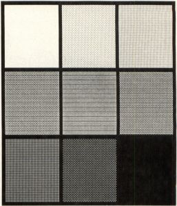
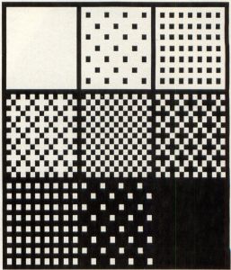
Figure 1 shows an example of the various levels of shading used by GEM, while Figure 2 presents a magnified view of the pixel patterns used. This is one way (actually, the most common way) of simulating shades of gray in monochrome. But it is not the only way, and it is certainly not the way we will be doing it.
We shouldn't need to examine an area of the screen to discern gray, but instead should be able to get that information from one and only one pixel. We should not see a pattern that looks gray; we should just see the gray. That's what we get with color monitors, and that's what I hope to accomplish here through a quality of the phosphors in the monitor's picture known as persistence.
A bright idea
Ever wonder how a light dimmer works? Those little electronic marvels that replace wall switches are showing up in more and more homes. They are small, cool running (the dimmer, not the bulb) and highly efficient—but it was not always this way. Before the advent of the transistor, one needed a very large, mechanically controlled rheostat to reduce the amount of current going through a light bulb. These rheostats also tended to generate quite a bit of heat; so mounting them in a wall was asking for trouble.
Nowadays, things are much simpler, and it's all because of an small electronic component known as a Triac. A Triac (the General Electric trade name for the device, by the way) is nothing more than a very fast, bidirectional, electronic switch. When wired in series with your common, garden-variety 100-watt light bulb it does an amazing thing—or rather, it is simply amazing what it doesn't do! It does not reduce the voltage or the current going into the bulb.
Instead, the Triac turns the bulb on and off very quickly, at a rate of 120 times a second. This switching effect is timed to synchronize with the up and down voltage swings that appear in your everyday 60-cycle AC house current, as illustrated in Figure 3A (the lamp operating at full brightness). Figure 3B shows the voltage present at the lamp with the dimmer circuit set to half brightness. The bulb has only enough time to reach the brilliance set by the dimmer when the power is abruptly turned off. It does this again and again 120 times each and every second. The bulb itself takes far longer than the &frac1120; of a second to visibly go from off to on and then off again. The thermal "persistence" of the filament provides the stability needed so that we don't all go bonkers from the flickering.
The phosphor material found inside a fluorescent lamp also exhibits persistence, though not as dramatically or for such a length of time as that of an incandescent light. Its operating parameters are not related to temperature. Rather, a fluorescent lamp works by passing a high voltage through a gas-filled tube that generates long-wave ultraviolet light. These ultraviolet rays strike the phosphor material that coats the inside of the fluorescent tube. The phosphor absorbs the UV light, thus causing it to glow with visible light. Oh, in case you're wondering, those "black light" bulbs that you see used at Halloween parties or in window displays are merely fluorescent lamps that someone forgot to coat with phosphor.
Now what does all this stuff about light bulbs have to do with monochrome monitors? Well, the interior surface of the picture tube found inside your monitor is similar to the internal makeup of a fluorescent light bulb; the difference being that the phosphor on the inside of a picture tube glows not because it is being hit with ultraviolet light, but rather from a head-on collision with a beam of electrons. The effect is the same in both cases: The phosphor gives off visible light and takes time to stop glowing once the source of excitation (either the ultraviolet light or the stream of electrons) is extinguished.
Just like in the movies
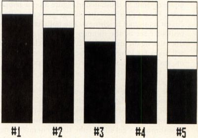
When we look at a monochrome screen, we are presented with a still image that is being flashed at us 70 times each second. If we were to take out every other frame so that we were presented with the sequence PICTURE, blank screen, PICTURE, blank screen, PICTURE and so forth, we would still see the original image but something strange will have happened to it: It seems dimmer. The phosphors are now given a chance to darken between frames of information. You might even notice a slight flickering effect. If we inserted two blank screen frames between our actual images, the sequence would seem darker still and the flickering effect more pronounced. The more blank screens, the darker the apparent image and the more pronounced the flickering.
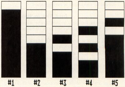
We can change the mixture of blank screens to data images to favor the data. PICTURE, PICTURE, blank, PICTURE, PICTURE, blank, etc., will seem brighter than the 50/50 mix originally tried, though it's not as bright as when we had no blank screens at all. Have you noticed that we can increase the number of different apparent brightness levels by increasing the number of frame sequences shown before repeating?
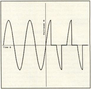
Figure 3B—Half Brightness
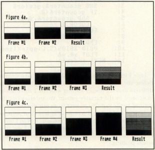
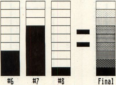
Since we want to have more than one level of gray on the screen at once, it would be silly to just insert "blank" frames. If we want graphics near the top third of the screen to be white, the middle third gray and the bottom black, all we really need are two alternating screens as shown in Figure 4A. Both frames show white at the top and black at the bottom with the middle third alternating. By merely adding extra frames to the sequence as shown in Figures 4B and 4C, we can generate three and four visible brightness levels.
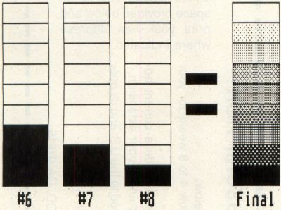
Each frame will be taking up 32,000 bytes of memory in your computer. A seven-frame sequence that will produce eight noticeable brightness levels (numbered 0..7) will require 224,000 bytes of free RAM to store. It will take &frac110; of a second to show these seven-frames before repeating, thus producing a now very noticeable flickering effect. A whopping 672,000 bytes would be needed to generate the 21 different frames needed to simulate all the possible brightness combinations that a color monitor can produce. Twenty-one frames not only use three times as much RAM space as our seven-frame example, but the flicker rate is three times more pronounced, taking a full &frac310; of a second to come full circle. It can no longer be classified as a flicker; more like a headache waiting to happen!
Dithering time
The technique of drawing noncontiguous frames until the specified gray value was reached was what I originally used and planned on using for the GFA BASIC code presented here; but I found a way to improve it that reduces the perceived level of flicker involved without really changing the picture. This improvement involves the use of dithering.
Now don't everybody jump down my throat with "But you said you weren't going to use dithering or fill patterns!" That's true, I'm not—not in the conventional sense anyway. Dithering, as it applies to computer graphics, usually means scrambling the pixel patterns in order to generate a blurred image. We normally use these blurred images (fill patterns, really) to generate tones of gray on the screen. But what if we don't scramble pixels? What if we dither the sequence that frames appear on the screen instead? Remember, I'm trying to blur the flickering effect and Figures 5A and 5B show what happens when we do that. Note that "time dithering" greatly reduces that flicker rate for grays near the middle of the scale.
The algorithm used is quite simple, as the following block of GFA BASIC will show:
1:    gcounter& = 0
2:    FOR index& = 1 TO gmax&
3:      SUB gcounter&, gcolor&
4:      IF gcounter & < 0
5:        ADD gcounter&, gmax&
6:        COLOR 1
7:      ELSE
8:        COLOR 0
9:      ENDIF
10:     VOID XBIOS(5, L : gptr%(index&), L : -1, -1)
11:     PLOT x&, y&
12:   NEXT index&
Line 1 initializes our accumulator variable counter to 0. Lines 2 and 12 define the limits of our FOR/NEXT loop that will take us through the different drawing frames starting with No. 1 and ending with the last frame as defined by the variable gmax&. We subtract our desired gray value as defined by the variable gcolor& from our working accumulator gcounter& in Line 3. In Line 4, if gcounter& is less than zero, we add the value of gmax& to it and set the drawing color to 1 as in Lines 5 and 6; otherwise, set the drawing color to 0 as seen in Line 8. Line 10 uses an XBIOS call to select the logical drawing frame area in RAM, and Line 11 does the actual plotting.
All quite simple, really. It is interesting to note that when this algorithm is modified slightly, it is the one used by the operating system to draw diagonal lines on the screen. We'll delve deeper into the working of these routines a little later on.
Lights, "camera," action!
So while the flickering has been greatly reduced, there is still some that can be seen, especially for very bright and very dim shades of gray. "So what's the point of all this if it blinks at you?" you might say. Well, I use my camera to take photos of the monitor's screen to help in illustrating articles. You see them in this article, for example. If I know that a certain photo is to appear on a black-and-white page, I prefer to shoot it off a monochrome screen. Unlike a color monitor, scan lines do not as readily appear in monochrome. There are just too many of them to be noticeable. The normal method of rendering grays in monochrome by using fill patterns is, however, very noticeable.
Remember that I said I use a camera to take screen shots? Well, photographic film exhibits an extremely high degree of "persistence" as an input device. This fact has been exhibited for decades in the field of astronomy where they direct light coming through a telescope onto a sheet of photographic film for hours on end, allowing the exposure to build up. That &frac110; or &frac310; of a second flicker rate will not be noticeable when the camera's shutter is left open for one or two seconds!
And now for something more BASIC
The GFA BASIC 3.0 routines presented here will allow you to plot, draw lines, shapes and text using multiframe gray scaling. For the most part, these routines are merely substituted for the standard BASIC graphics commands like PLOT, LINE, DRAW TO, TEXT, CIRCLE, BOX, etc. As an example, let's say that we want to draw a circle in the middle of our monochrome screen with a radius of 50 and a gray-scale value of 4. Normally we would use the command:
CIRCLE 320, 200, 50/PX
to accomplish this. We, however, want to draw in several different frames to get the gray effect, so we call the GFA BASIC procedure @gcircle as follows:
gcolor& = 4 @gcircle (320, 200, 50)/PX
which first sets the gray color value to 4 and then plots the circle in all the frames. This assumes that we've already set aside or dimensioned the different areas of RAM that will hold the frames and initialized variables that point to them. All of the procedures and global variables used by these gray-scale routines start with the letter g for gray. There is no real reason for this; it just makes it easier to debug and document the code.
Turning gray
Now, lets get down to the "meat and potatoes" of the program and examine how the Mono-Gray procedures work. The first block of code to get executed (or else none of this will work) is:
@ginit(planes&)
which happens to be one of the longest pieces of code here and with good reason. It lays the groundwork for the rest of the Mono-Gray code to work in by reserving screen RAM, initializing pointers and variables and clearing the screen. It is called as shown above by substituting the number of planes you want to use as the parameter. For example, if you want to be able to display eight different brightness levels numbered [0..7], this would require seven planes. Four brightness levels numbered as [0..3] would require three planes. The number of planes specified must be an integer greater than one. Specifying too large a value (each plane using up 32,000 bytes) would normally produce an "out of memory" error, but I've added some code to check for this instead. Please note that this procedure can be called only once when you run your program, otherwise it would try to dimension arrays twice had a little bit of error-checking code not been added.
Let me also explain the variables that are found in @ginit so you'll have a better idea as to what is going on, but more importantly, so you won't use them in your own code.
gmax&—This holds the value passed to the @ginit procedure and is used by just about every Mono-Gray routine. There is no reason that your code should change this, but it can be read to determine the number of planes used. Most of the variables are like this so I'll only tell you which ones are safe to use and why. Also, most of these variables you'll see here are two-byte word-length variables found in Version 3.0 of GFA BASIC. They can be converted to 2.0 style integers if need be. I prefer 3.0 and use it exclusively.
gptr%( )—An array of long integers that point to the beginning of each frame of screen RAM. They are used by all those XBIOS commands to change drawing and/or viewing frames.
gram|( )—A large array of type BYTE to hold all the screen frame data.
glogbase%—Holds the address of the original area of screen RAM so we can put it back when we're done. Used by the @gexit procedure.
gcolor&—This one you do want to include in your code, for it allows you to specify the drawing color. Just set this variable to the selected shade of gray before calling the drawing routines for that color. Initialized here to gmax&.
glastx&—Set to the X-coordinate endpoint by the @gplot, @gline and @gdrawto routines.
glasty&—Y-coordinate match for glastx&.
Our next routine is called after the drawing is complete. Its job is to cycle through the graphics frames in tune with the vertical blank routines (so there are no visible glitches) to display the total picture. It is called by the command:
@gshow
It requires no parameters since it gets all its data from variables that were set up in @ginit. The code is written to exit when either mouse button is pressed, but can be easily modified to trigger on keyboard input or via a built-in time delay. Upon exiting, you will be once again looking at the first Mono-Gray screen.
We even have a procedure to erase all of the Mono-Gray drawing screens, which also doesn't require parameters. Since it is similar to the GFA BASIC command CLS, we give it a similar name and call it as follows:
@gcls
Before exiting our BASIC program, we need to put the screen RAM back to where it was before we ran the @ginit procedure. This is accomplished by the routine:
@gexit
The PLOT thickens
Now we get down to the nitty-gritty and give the procedures that do the actual writing to the screen (screens?). We'll start off with our routine to plot dots, which is called as follows:
@gplot(x&, y&)
This is just like the GFA BASIC statement PLOT x&, y& with the values of the variables, constants or numeric expressions being passed following the same rules. The coordinate values are best limited to [0..639] for X and [0.399] for Y. This holds true for the other gray-scale output routines.
The plotting color (or grayness in this case) used in all these graphics routines is determined by the value of the variable gcolor&. To select a new shade of gray, simply equate this variable to the new value like this:
gcolor& = (5 + x)/2
Note that the value used must be a positive integer, less than or equal to the value of gmax& as defined in the routine @ginit().
The next two commands are related in that they both draw lines to the screen and look like this:
@gline(x1&, y1&, x2&, y2&)
@gdrawto(x&, y&)
The first procedure, @gline, is equivalent to the GFA BASIC statement LINE x1, y1, x2, y2 and requires the starting and ending X and Y coordinates to work. The @gdrawto procedure is akin to the command DRAW TO x,y in that it also draws lines but takes the starting point from the last coordinate pair used by the most recent call to @gplot, @gline or @gdrawto. You can draw connected lines by calling the @gdrawto routine a number of times. Note that you can use the BASIC statement DEFLINE to change things such as line style, line width or specifying round, square or arrowshaped line ends. DEFLINE can also be used with the upcoming code to change the characteristics of drawn boxes and circles.
@gbox(x1&, y1&, x2&, y2&)
@gpbox(x1&, y1&, x2&, y2&)
@grbox(x1&, y1&, x2&, y2&)
@gprbox(x1&, y1&, x2&, y2&)/PX
The above are the four routines to generate boxes on the screen. In the order that they appear above, they generate boxes, filled boxes, boxes with rounded corners and filled boxes with rounded corners.
The DEFLINE statement, as explained with the plotting and line drawing routines, can be used to change the characteristics of the outer box. The filled box commands (as well as the filled circle and ellipse commands to follow) may also use the DEFFILL statement to select a specific fill pattern.
@gcircle(x&, y&, radius&)
@gpcircle(x&, y&, radius&)
The above call draws circles and filled circles respectively. Simply specify the X and Y coordinates for the center of the circle as well as its radius and it will be drawn in the color specified by the variable gcolor&.
@gellipse(x&, y&, rx&, ry&)
@gpellipse(x&, y&, rx&, ry&)
These calls make available to us the ellipse drawing routines found in GFA BASIC. The parameters that substitute for rx& and ry& determine the radius from center in the horizontal and vertical directions. I guess there is no easy way to draw an ellipse that is set at a 45-degree angle!
We have modified the @gcircle and @gpcircle routines to allow them to handle drawing parts of a full circle by specifying the starting and ending angles in &frac110; of a degree [0..3600]. These procedures are:
@garc(x&, y&, radius&, angle1&, angle2&)
@gpie(x&, y&, radius&, angle1&, angle2&)
They are identical to the code that generates circles and, correspondingly, filled circles with the addition of the angle parameters.
Finally, the same thing has been done to produce partial ellipses and filled ellipses with:
@gearc(x&, y&, rx&, ry&, angle1&, angle2&)
@gepie(x&, y&, rx&, ry&, angle1&, angle2&)
Text may be presented on the screen in gray scale by the use of the Mono-Gray procedure:
@gtext(x&, y&, string$)
This procedure takes the same parameters as the GFA TEXT statement to specify the starting X and Y coordinates, as well as the string to write. The DEFTEXT statement can be used to change the characteristics of the drawn text. Bold, light, italics, underlined, outlined or any combination of the above text attributes can be selected with DEFTEXT, as well as specifying the angle and size of text.
To determine the shade of gray of a particular point on the screen, use the following function:
gray&=@gpoint(x&, y&)
This is essentially the opposite of the plotting routines in that it adds up the values found by the BASIC function POINT(x, y) for the same coordinates on all the different planes and returns the total.
To FILL or not to FILL
I had decided to leave out the implementation of the graphic statement FILL that is found in GFA BASIC, since I was sure that I couldn't guarantee it would work for all cases. For example, say you wanted to draw a circle in Shade 1 but fill it with Shade 2. Shade 2 requires writing to two separate graphics planes, whereas the circle drawn in Shade 1 appears in only one plane. The fill operation would work properly in the first plane, filling in the circle, but the circle would not be there when it came to fill the second plane. The fill operation would then overflow the area. That's nasty, so I'd decided not to do it.
Then I decided to, in fact, do it—provided that those who tried to implement the routine:
@gfill(x&, y&)
If you implement the routine, you must understand the aforementioned limitations. It can only be guaranteed to work if the fill color (set by the variable gcolor&) matches the color of the closed figure you wish to fill, or if the closed figure's color is the maximum allowed by the resolution specified in @ginit( ), which is also the value of the Mono-Gray variable gcolor&. It will also always work if the fill color is set to 1 (the lowest brightness before total black), and the color of the object to be filled is at least one. There are most certainly other color combinations that will produce the desired results, but these depend on the gray resolution used. If someone can come up with a mathematical formula that can test for overflows produced by the @gfill procedure, I'd certainly like to see it.
Listings and such
The GFA BASIC code to do all of the above can be found in Listing 1. This listing also contains a short demo program to exhibit some of the features of Mono-Gray. Listings 2 and 3 can replace the demonstration code in Listing 1 to show off other features of the program. If you do not wish to type in these programs, you can find them on this month's disk version or as downloadable files in the ST-LOG SIG on DELPHI.
Next month, I'll present more BASIC code to convert and display low resolution DEGAS and Tiny files using the techniques presented here. In the meantime, I'll be working on a machine language desk accessory for a future issue that will display these, as well as Neochrome and Spectrum 512 files. Until then, may your blue skies be gray!.
Charles Bachand, when not tooling around town in his 300ZX, can usually be found racing R/C cars or busily managing his own area on DELPHI, the Hobby SIG. His username is appropriately, BACHAND.