TUTORIAL
Software Engineering:
System Specification and Analysis
by Karl Wiegers
After receiving a Ph.D. in organic chemistry, Karl Wiegers decided that it was more fun to practice programming without a license. He is now a software engineer in the Eastman Kodak Photographic Research Laboratories. He lives in Rochester, New York, with his wife, Chris, and the two cats required of all ST-Log authors.
What's the first thing you think about when you decide to begin a new software project? I hope your answer is, "What's the intended output of this program?" The output of a program might be described very differently, depending on whether you're contemplating a weather-predicting program or a flashy arcade-style game. But all computer programs produce some kind of output, and it helps immeasurably during the programming if you know exactly what that output is.
In the olden days of computer programming, the issue of specifying precisely what a software system was to accomplish often was skirted, rather than being confronted head-on and beaten into submission. The results were predic-table: Systems were delivered to end users far behind schedule, they cost a lot more than anyone expected, and all too often their performance bore only a vague resemblance to what the end user really had in mind. "Don't worry about the details now," the system analysts said. "This baby will be so flexible that we can change it later on when you decide what you really want." The analysts were wrong; their customers were unhappy.
Contemporary software development efforts rely more and more on systematic "software engineering" methodologies. A vital aspect of those methodologies is a structured, comprehensive approach to analyzing the problem that the software system is being constructed to solve, thereby defining the system's intended functions. This is a critical first step, to be taken before any code is written if you truly wish to create a high-quality system. In fact, good specifications are fundamental to any problem-solving venture, from building a box to keeping your firewood dry to landing a man on Mars.
"But," you say, "I successfully programmed for years on an Atari 8-bit computer without using any of these newfangled ideas." So did I. And when you're dealing with small memories and low-powered computers, you can get away with more casual development methods much of the time. But the new generation of microcomputers, such as the Atari STs and their big brothers of the Mega persuasion, can run programs vastly larger than could be handled by the 8-bits. These programs often are written by teams of programmers, and they might involve dozens of program modules all spliced together to create the final product. A systematic, structured approach can give tremendous improvements in productivity, quality and reliability for such systems.
Some software engineering gurus believe that about 40% of the effort put into a complex software system should be devoted to defining the system through structured analysis and design activities. Only 20% of the time should be spent on the implementation step of actually writing code, with the remaining 40% used to integrate the pieces of the system and test for proper behavior. In this article we'll begin a discussion of the software engineering process by examining the principles and tools of structured analysis and system specification.
Where do I begin?
Amazingly enough, at the beginning. Many programmers gloss over the beginning and dive right into a source code editor. Only later do they realize how much easier life would be if they had a plan, a design. I look at it this way: If I don't know what I'm trying to accomplish, how will I know when I'm done?
Admittedly, a thorough, structured analysis isn't something most hobbyists want to spend their time on. They (including me) want to write code. And it's true that the problem of system specification is less serious when only one person (you) is working on the project. But believe me, if you read the rest of this article and try to apply some of the ideas to your next project, I think you'll recognize the benefits. Software engineering methodologies can do for complete systems what structured programming methods do for individual program modules. The long-term payoff comes during the maintenance phase of a software project, when you're trying to add additional features or eradicate bugs. A high-resolution roadmap of your system makes navigation a whole lot easier.
The goal of system analysis is to come up with a requirements document which will serve as the guiding beacon for the rest of the development effort. In the olden days, these often belonged in the Victorian novel category: huge, unwieldy and incomprehensible. Nobody ever read the whole thing. In the 1970s, though, new methods were invented that use graphics for much of the requirements document. The focus is on communication, and we've all learned that visual communication through graphics can be much more effective than reading volumes of text. So, modern requirements documents contain lots of pictures. How do you draw a picture of a software system? We'll see shortly.
Of course, it's unrealistic to expect that the system requirements will never change once they're written down. Most projects go through many iterations of refinement and enhancement. You probably won't be able to permanently freeze the requirements, but the more you know about the needs before you begin writing code, the better off you are. The idea, then, is to construct the system such that it can readily accommodate changes without collapsing under its own weight. This is the goal of structured analysis (in the early phases), structured design (in the middle stage), and structured programming (in the later phases).
To explore some of the ideas and techniques of structured analysis, let's use a real example, an educational chemistry game called Reaction Time that I wrote once upon a time on an 8-bit Atari in assembly language. In Reaction Time, a player moves chemical formulas and numbers from specific areas on the screen into an empty line representing a chemical equation. The idea is to build valid chemical reactions by properly combining four elements or compounds from a specified list of formulas. Each reaction set contains 15 different formulas, and between nine and 16 valid equations can be constructed in each set. The program has seven different reaction sets, representing different aspects of basic chemistry. The player gets ten points for each correct equation and six points for each equation in which the formulas are correct but the coefficients are not; he loses five points for each incorrect equation.
See? You just read the entire statement of purpose for Reaction Time. And you didn't even have to know anything about computers (and not much about chemistry). Notice that this description of the system didn't say anything at all about the programming language that would be used, the kind of hardware the program would run on, or any other details. We're beginning with a fairly abstract statement of what the system will do.
Now we must refine this idea into successive levels of detail, such that we not only gain a thorough understanding of what we wish to accomplish, but also get enough information so that we can eventually write a program. Along the way, I like to create a written, numbered list of all the functions the system must perform. Then, as I design the system, I'm less likely to overlook something inadvertently.
Model making
With the statement of purpose firmly in mind, we want to begin building "models" of our software system. These models will graphically represent the system at various levels of detail. An important goal of building these models is to break the system down into logical pieces that fit together so that there aren't any gaps when we assemble the final product. Come to think of it, this isn't all that different from building a plastic model of an F-15 jet fighter. Obviously, we don't use molded plastic parts and glue for constructing models of software systems; we'll get to the model components in just a bit. First let's think about the different kinds of models we might want to create.
During the analysis phase, you begin by building a "logical" model of the system. This is a conceptual depiction of what the software system is supposed to do, showing its connections to the outside world (that is, everything in the universe that isn't a part of your system, yet which interacts with it in some fashion). The logical model is independent of any implementation details, showing just what happens and not how it happens.
After creating a clear picture of your system functions on a logical basis, you build a "physical" model of the system. (I don't mean a physical model in the sense of ice cream sticks and playing cards, but rather a graphical model of the ultimate physical system you intend to create.) This physical model will include implementation details such as hardware- and software-specific features. An example might be a program that will use GEM on the Atari ST for the user interface. The same program written for an IBM PC might have a rather different physical model, because of the different user environments. However, these two physical models would be based on the same logical model, since the system functions would be the same in both cases.
Actually, you may well build more than one physical model. After all, there's almost always more than one way to solve a particular problem. It's highly advisable to consider all the approaches you can think of early on, and then choose the one that makes the most sense. Also, this makes you feel much less foolish than if you dive right in and then discover a far better approach after you're neck-deep in design flaws.
Sometimes (although not usually when writing for microcomputers) the system being developed represents an automation of an existing system. For example, converting a process that is currently performed manually into one in which a computer performs all or part of the tasks of the process fits into this category. In cases like this, the proper starting point is to build a physical model of the current, manual process. This helps to identify all the functions and components of the current system, in terms of the documents, people, and equipment actually involved in the execution of the process.
From that specific, physical model you can derive a logical model of the current system. The logical model is basically the physical model with the implementation details removed. Who needs to know that Ralph sorts the mail in room 145? All you need to know on a logical basis is that the mail gets sorted. Then, the logical model of the current system can be used as the starting point to generate the logical model of the new, automated system. We won't worry anymore about this aspect of system specification, since I suspect you won't be starting with an existing manual system of any kind when you sit down to write the ST arcade game of the year.
Context diagram
Okay, let's get started with the logical model for Reaction Time. The modeling tool used to represent our system at its most abstract level is called the "context diagram." Figure 1 shows the context diagram for Reaction Time. Our system is represented by the circle labeled "Chemical Reaction Game." (Remember, this is a logical model, so I won't even give it an official name here.) The objects in rectangular boxes are external to our system, yet they have some communication with the system. These are the player, a joystick and a joystick trigger.
Figure 1. Context Diagram for Reaction Time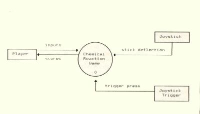
The lines with arrowheads indicate the communication between the external objects and the system itself; they represent data flowing from one object to another. In this case the player is supplying something called "inputs" to the system, and the system gives him back something called "scores." The joystick's contribution is labeled "stick deflection," and the joystick trigger supplies a "trigger press."
The context diagram is a special case of a very important modeling tool called a "data flow diagram" or DFD. There are really only four kinds of objects in a DFD: processes (shown as circles, or sometimes as rounded rectangles; sometimes called a "bubble"); externals (shown as rectangles; sometimes called "terminators"); data flows (shown as lines with arrowheads); and data stores (but not on the context diagram; stay tuned). All of these objects must be labeled, as they are in Figure 1. On the context diagram only one process is shown, which represents the entire system.
The context diagram often is labeled with a zero, as in Figure 1. This indicates that, on another piece of paper, we are going to peer inside this one bubble and see what it contains in more detail. The magnified view of object "Chemical Reaction Game" will be labeled the zero-level diagram, and it will be another DFD containing the four kinds of objects mentioned in the previous paragraph.
I can hear you now. You're saying, "I'm never going to bother drawing context diagrams and data flow diagrams, because I don't need to go through this analysis jazz for my programs. I've got it all in my head." Well, that may be. However, read on, because these same diagramming tools are also used in the structured design phase, and I'll guarantee you that you don't have the entire design for a program of more than 100 lines in your head. DFDs really do help you understand both what you want your system to accomplish (during analysis) and how to go about accomplishing it (during design).
Okay, I admit it, this context diagram has a little bit of physical model flavor. After all, I did mention physical "things" like a joystick and a joystick trigger, yet I didn't say anything about a mouse. It's sometimes difficult to completely separate the what of the system from the how. My own experience has been that, for smallish software projects, only one model is really necessary at the analysis step, and that is the physical model. In the case of Reaction Time, there wouldn't be an enormous difference between the logical and physical models of the new system. And, since I'm not really converting an existing system, there's no need to create physical or logical models of a current system. Your choice of which models to build during system analysis should be dictated not by dogma, but by the scope, nature, and complexity of your application.
Partitioning
The next step of analysis is to start breaking down your system into smaller pieces, by turning your microscope on to the context diagram. Begin by drawing the zero-level data flow diagram; the one for Reaction Time is shown in Figure 2.
Notice that Figure 2 contains several processes, numbered with integers. The fundamental definition of a process is something that converts inputs into outputs—nothing fancier than that. Basically, this is what all computer programs do, so we must be on the right track. Every function performed by the Reaction Time system must be represented by a process on the zero-level diagram. After all, the zero-level DFD is just an expansion of the single bubble on the context diagram, which contained the entire system, so this makes some sense.
Figure 2. Zero-Level Diagram for Reaction Time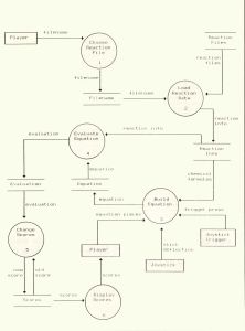
The step of breaking the entire system into separate logical functions is called "partitioning," and it is mighty important. A certain amount of partitioning will be intuitively obvious. Some functions will just jump out at you and exclaim, "I'm a process, I'm a process!" But often the separation between one process and another won't really be clear. You may find that there are several ways you can think about splitting parts of the system into separate logical processes. Don't feel bad if it takes a few tries to get it right.
We'll go through partitioning again when we enter the design phase, in which the physical model of the new system (one product of structured analysis) will be used to figure out exactly how we are going to implement our system. We'll talk more about the importance of partitioning and modular program design in future articles, but trust me when I say yet again how important it is to do a careful, thoughtful job of partitioning your system.
Data-flow diagrams
Since they are so important, let's take a closer look at the anatomy of a data flow diagram. Please turn again to Figure 2. I have partitioned the Reaction Time system into six main processes: Choose Reaction File, Load Reaction Data, Build Equation, Evaluate Equation, Change Scores and Display Scores. These processes are numbered from 1 through 6.
Important rule No. 1 for DFDs: A DFD does not imply anything about the sequence in which processes are carried out. (There's an exception to this, which we'll get to later on.) The numbering system in each level of a DFD is arbitrary. You shouldn't be tempted to look at Figure 2 and conclude that process 1 always takes place before process 2. Of course, some of your partitioning will be based on just such sequential thinking, but the general rule is to not attempt to infer sequence information from a DFD. This is a very important distinction between the data flow diagram and a diagramming tool with which you may be more familiar, the flowchart.
Important rule No. 2 for DFDs: All externals shown on the context diagram must appear on the zero-level diagram. Recall that the external objects are shown in rectangular boxes; Reaction Time has the three externals labeled Player, Joystick and Joystick Trigger. The zero-level diagram shows more detail about exactly how these externals connect to the different processes in the system. You see that Player appears in two places in Figure 2. This is just a matter of graphical convenience, so the data flow lines don't cross over one another.
Think of the context diagram as a "parent" diagram, and the zero-level diagram as its "child." It's important that each child DFD be consistent with its parent DFD as far as things like externals and data stores go. Those objects represent the connections between a process and either the outside world, or other processes within the system. For example, if we expanded process 1 from Figure 2 into yet a more detailed DFD, it had better have input from the external called Player and it had better generate output to the data store called Filename. You could invent other data stores that functioned entirely within the subprocesses of process 1, but these two key objects absolutely must be present.
Important rule No. 3 for DFDs: Bubbles don't talk to bubbles. That is, you shouldn't have a data flow line going directly from one process to another. Instead, it should go into a data store, with a second flow coming out of the data store into the second process. Some DFD advocates don't worry about this convention, but I've come to appreciate it, for reasons that will become more obvious when we talk about structured design. Patience, please.
Just what is a data store? Nothing more than a logical grouping of some information that's used in your system. In a logical model, a data store just represents a block of data. In a physical model of the current system, a data store could represent a paper form that's filled in by one person in your organization and handed to another person. In a physical model of the new system, a data store might be a disk file. At this stage of our analysis, the nature of each data store isn't as important as its contents. And we'll wait to think about actual file formats until much later.
The data stores in Figure 2 have labels like Filename, Reaction Files, Reaction Info, Equation, Evaluation and Scores. Notice that many of the data flows have exactly these same names. This should come as no surprise. After all, it is data that is flowing from one process to another, and data stores are simply collections of data. However, sometimes a process needs only part of the data in a particular store.
For example, in Figure 2 there's a data flow named Chemical Formulas coming out of a data store named Reaction Info. How is this possible? Well, we can conclude that the thing called Chemical Formulas must be just one part of the thing called Reaction Info. On the other hand, process 4 wants everything out of Reaction Info, so the flow has the same name as the store. Make sense? In our next software engineering installment, we'll talk about exactly how to define all the objects in a system model.
Important rule No. 4 for DFDs: Label all data flows. If you can't give a data flow a reasonable name, odds are pretty good that you don't have a clear idea of what data is being represented by that flow line Repartition your system until all the flows can be logically named. And things like "Data" and "Information" do not in themselves constitute reasonable names, so don't think you can be sloppy at this stage.
Some DFD conventions allow you to leave a data flow unlabeled if and only if the flow is connected to a data store. In such cases, the flow label is assumed to be the same as the name of the store. Of course, if the flow is supposed to represent only a portion of the contents of the store, as we just saw, you'd better give it a separate name. In my DFDs, any unlabeled flow will indeed indicate that the flow name is the same as the name of the data store to which it is connected.
We'll leave data flow diagrams for now, but they'll be back. There are some other important rules for DFDs we still need to talk about.
Data Dictionary
Even in this tiny model of this little system, we have already introduced no less than six processes, three externals, six data stores and 18 data stores (if my count is correct). How in the world are we going to keep track of all these names and what they mean? And how are we going to keep track of things like the fact that the data flow Chemical Formulas is a part of the data store Reaction Info? We need another tool, called a "Data Dictionary." The name is pretty self-explanatory.
But, we don't have time to talk about data dictionaries today. Please tune in next time, when we'll continue our discussion of structured analysis and system specification. Once you learn about data dictionaries, your life will be transformed. Well, maybe that's a slight exaggeration, but it's certainly true that using these analysis and design tools will speed your metamorphosis from a casual programmer to a genuine software engineer.
Bibliography
The main reference for structured analysis and system specification is a book called (guess what) Structured Analysis and System Specification, by Tom DeMarco. If you think you'll use any of these methods, you definitely want to have this book!