TUTORIAL
Sprite PROGRAMMING
by Kelly Schreiner
Kelly Schreiner has been programming Ataris for approximately six years. He enjoys programming his 520 ST in both 68000 machine language and C, and is currently studying to become an electronic engineer.
For those of you who grew up programming on the 8-bit Ataris as I did, ST sprite programming should be a fairly routine task, because the ST's sprites are analogous in many ways to the Player/Missile graphics we were accustomed to on the 8-bit machines. And for those of you that have never programmed either sprites or Player/Missile graphics, this is the perfect time to learn sprite programming for the ST computer. But first, let's make some comparisons between ST sprites and Player/Missile graphics, just so everybody knows what a sprite is to begin with.
ST sprites and Player/Missile graphics are both user definable bit-block images stored in memory that can easily be moved around the screen independent of the background drawing. They both can have depth, (meaning that the first object drawn can pass in front of the second object, the second in front of the third and so on), and they both can have only one color. (Unless, of course, two or more objects of differing colors are overlayed on top of each other). Both Player/Missile graphics and ST sprites are commonly used in games for arcade-type action on their respective computers.
Now that the similarities between ST sprites and Player/Missile graphics have been looked at, let's examine the differences between the two. One of the major differences between ST sprites and Player/Missile graphics is that the ST sprites are purely software-based sprites, not hardware-based, like Player/Missile graphics. The ST sprites are also limited in size; they measure 16 × 16 pixels instead of 8 pixels wide by either 1-128 or 1-256 pixels high for Player/Missile graphics. The ST sprites are considerably easier to create than Player/Missile graphics though, and you can have practically as many sprites in a program as you want compared to the four players along with their missiles that Player/Missile graphics offers.
As I said earlier, sprite programming on the ST computer is a relatively easy task to accomplish. That is, once you know how! The main reason for this is the fact that most of the work related to sprite programming is already done for you in the Line A opcodes, $A00D (DRAW__SPRITE) and $A00C (UNDRAW__SPRITE).
By using the DRAW__SPRITE opcode, ($A00D), the sprite's X/Y coordinates on the screen can be established along with the sprite to be seen and its associated background buffer. The background buffer is needed to temporarily store the background behind the sprite, so that when the UNDRAW__SPRITE opcode is called to erase the sprite, the background can be restored to its original condition, just like it was before the sprite was drawn over it.
That's basically all there is to programming sprites on the Atari ST. Now we'll get down to the heart of the matter and take an in-depth look at how to program the various structures needed to produce ST sprites. (This is also the code to use for drawing and erasing the sprites normally, instead of the macro functions used in the program listing, just in case you don't have a macro assembler.)
One of the most important things you need to understand to be able to program sprites on the ST computers is the use of the Line A opcodes. These opcodes are the very heart of the ST's powerful graphics capabilities.
The software developers of the ST have made use of the fact that the 68000 processor used in the Atari ST computers has two groups of opcodes which it does not understand, and which consequently generate a software interrupt when encountered in a program. These opcodes begin at memory locations $Axxx and $Fxxx. The Atari ST uses the $Axxx opcode trap, referred to as the Line A Handler, to access its graphics routines. The trap handler that processes this trap recognizes word opcodes that begin with the bits 1010 (hexadecimal A) as unimplemented instructions and then jumps through a special exception vector, which in the ST's case points to the Line A routines. The lower four bits of the word opcode used contain the number of the routine to be accessed. Only values between $0 and $E are allowed here. That means that a total of 15 different opcodes are available for the Line A graphics routines. This number includes the initialization opcode, though, so there are actually only 14 graphics routines. In this demo program only the word opcodes $A000, $A00C, and $A00D are used, so I will confine myself to describing those.
In order to use the Line A opcodes you must first label the word opcode functions you want to use in your program. Here is the way these functions are labeled in the demo program SPRITES.
LINE-AI              = $A000  ;Initialization opcode
DRAW-SPRITE  = $A00D  ;Draw sprite opcode
UNDRAW-SPRITE        = $4A00C ;Erase sprite opcode
The next step is for you to initialize the Line A routines for use in the program. The opcode $A000, Initialize, is used to do this; it determines the address of the Line A routines. After calling this function, data register D0 and address register A0 point to a table with the starting address of the Line A variables. Address register A1 points to a table with the starting addresses for the three system font headers, and address register A2 points to a table that specifies the starting addresses of the 15 Line A opcodes. There's no parameter required for this function, so all you have to do is call the word opcode label that you specified for the $A000 (Initialize) function.
In order to draw a sprite onto the screen there are three things that need to be discussed. These are the DRAW__SPRITE opcode, the sprite definition block, and the sprite's background buffer. We will look at each of these structures individually.
The Line A opcode $A00D, DRAW__SPRITE, draws the desired sprite to the screen at the specified X/Y coordinates. To use this opcode the first thing you have to do is move the sprite's X coordinate into data register D0. Then, you have to move the sprite's Y coordinate into data register D1. After setting the sprite's screen position, you need to load the effective address of the sprite's definition block into address register A0. Finally, you must load the effective address of the sprite's background buffer into address register A2. Having done all this you simply call the DRAW__SPRITE function by using the word opcode label that you defined earlier. Here's an example of the process:
MOVE #150, D0
MOUE #100, Dl
LEA SPRITE1, A0
LEA SPRITE1_BUF, A2
DC.W DRAW_SPRITE
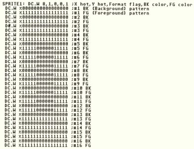
The sprite definition block mentioned above is a block of continuous memory that contains a total of 37 words that describe the sprite's appearance on the screen. This definition block must contain the following information:
Word 1 : X offset to sprite's hot spot
Word 2 : Y offset to sprite's hot spot
Word 3 : format flag (0 = VDI format, 1 = XOR format)
Word 4 : background color
Word 5 : foreground color
The next 32 words contain the desired sprite pattern. The pattern must be in the following order:
Word 6 : background pattern of top line
Word 7 : foreground pattern of top line
Word 8 : background pattern of next line down
Word 9 : foreground pattern of next line down
The first two words of the sprite definition block as mentioned above are the X/Y coordinates of the sprite's "hot spot." This coordinate set actually specifies the active point of the sprite. This is the point from which the sprite is drawn relative to when the DRAW__SPRITE opcode is called. The next word in the sprite definition block, Word 3 is the format flag. This flag tells the DRAW__SPRITE routine how to display the sprite's foreground and background in relationship to each other. The format flag usage is as follows:
—VDI Format—
| FG | BK | Result |
| 0 | 0 | The background (BK) appears. |
| 0 | 1 | The color in Word 4 appears. |
| 1 | 0 | The color in Word 5 appears. |
| 1 | 1 | The color in Word 5 appears. |
—XOR Format—
| FG | BK | Result |
| 0 | 0 | The background (BK) appears. |
| 0 | 1 | The color in Word 4 appears. |
| 1 | 0 | The pixel on the screen is XORed with the foreground (FG) bits of the sprite. |
| 1 | 1 | The color in Word 5 appears. |
Words 4 and 5 of the sprite definition block as stated before specify the sprite's background color and foreground color, respectively. The background (BK), color for the sprites should be set to a value of 0 or else the sprite will appear as your bit pattern design imprinted upon the top of a colored square. The foreground (FG) color can have any value between 1 and 15 depending upon which screen resolution you are currently using. The remaining 32 words of the sprite definition block contain the bit pattern for the image you want to display. Here's an example of a sprite definition block:
Now that we know how to put a sprite on the screen, we must be able to save the backgound behind the sprite so it can be put back once the sprite is moved. The sprite background buffer as mentioned earlier in this article does that very thing; it holds the background behind the sprite, so that when you move the sprite, the background beneath it can be restored to its original condition. This buffer must be 74 bytes long for high resolution, 138 bytes long for medium resolution, and 266 bytes long for low resolution. The difference is caused by the number of bit planes involved for the different screen resolutions. In low resolution the ST's screen needs a total of four bit planes to display the 16 colors normally available at any given time in that mode. The medium-resolution screen requires only two-bit planes to display the four colors available in that mode, while the high-resolution screen needs only a one-bit plane to display the monochrome image it produces. The formula used to determine the buffer length needed is N*64 + 10 where N is the number of bit planes.
Here's an example for all three resolutions:
SPRITEl_BUF: DC.B 74  ;high
SPRITE1_BUF: DC.B 138 ;med.
SPRITE1_BUF: DC.B 266 ;low
Once you know how a sprite is displayed on the screen and how to save into a buffer its background for later use, all that's left to learn is how to use that buffer to restore the background behind the sprite to its original condition. The routine used for this function is the Line A opcode $A00C, UNDRAW_SPRITE. This opcode has only one parameter. It is called simply by loading the effective address of the appropriate sprite's background buffer back into address register A2. You then call the UNDRAW_SPRITE function by the word opcode label that you defined earlier in the program.
In the demo program SPRITES, the INITIALIZATION, DRAW_SPRITE, and UNDRAW_SPRITE functions are put into macro form. The format of these calls are as follows:
LINE_AI = $A000 :label the initialization function
DRAW_SPRITE = $A00D :label the Draw__Sprite function
UNDRAW_SPRITE = $A00C :label the Undraw__Sprite function
LINE_A_INIT :do the Initialization function
MOVE_SPRITE X,Y,pointer to sprite definition block, pointer to the sprite's background buffer
ERASE_SPRITE pointer to the sprite's background buffer.
The macro definitions themselves look as shown in Figure 1.
LINE_A_INIT:MACRO
 DC.W LINE-AI    ;do the INITIALIZATION function
 ENDM
MOVE_SPRITE:MACRO $\1, $\2, S\3, $\4
 MOVE \1,D0         ;X position parameter
 MOVE \2,D1         ;Y position parameter
 LEA \3,A0          ;pointer to the sprite definition block
 LEA \4,A2          ;pointer to the sprite's background buffer
 DC.W DRAW_SPRITE   ;do the DRAW-SPRITE function
 ENDM
ERASE_SPRITE:MACRO $\1
 LEA \1, A2          ;pointer to the sprite's background buffer
DC.W UNDRAW_SPRITE  ;do the UNDRAW_SPRITE function
 ENDM
These macros are optional. If you don't have a macro assembler like AssemPro or its equivalent then you will have to use the coding discussed earlier in this article.
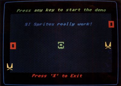
The demo program SPRITES is set up to use the low-resolution screen of the ST, although it will work in medium resolution. The program starts by drawing three stationary sprites of differing colors in the middle of the screen and two movable sprites in opposite corners of the screen. A prompt will then appear asking you to press any key to start the demo. After pressing a key, the two moveable sprites will begin to travel smoothly across the screen in opposite directions. They will continue to loop like that for about two minutes, and then you will be asked to press "X" to exit the program.
The smooth sprite animation achieved in this demo is accomplished by using the XBIOS function #37, (WVBL). This built-in XBIOS function is very interesting; it waits for the next picture return to occur and then synchronizes the following graphic output to it, whatever graphic output that might be. In the demo program the WVBL call is made right before the sprite is erased, thus insuring a smooth look for the sprite's movement to its next position. Here's an example of WVBL call:
MOVE.W #37,-(SP) ;WVBL function #37
TRAP #14         ;Call XBIOS
ADD.Q #2,SP      ;Restore the stack
(The demo program uses a macro for this function too. Since there are no parameters for this call all you have to do is put the WVBL call right before whatever graphics you want to synchronize with the picture return.)
The following macro definition for WVBL was used in the demo program:
WVBL:MACRO
 MOVE.W #37,-(SP) ;XBIOS WVBL function
 TRAP #l4         ;Call XBIOS
 ADDQ.L #2,SP     ;Restore stack
 ENDM
figure 1