Commodore 128 Machine Language
Jim Butterfield, Associate Editor
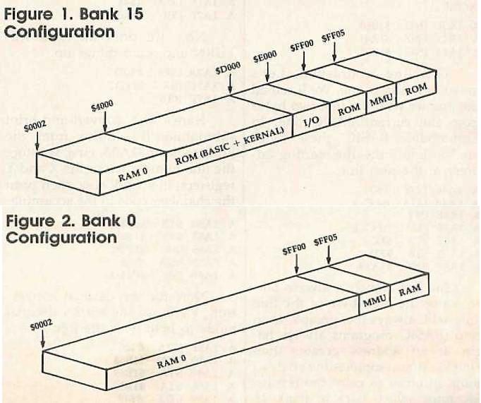
In this installment, Jim Butterfield delves further into the subject of memory configurations on the 128.As mentioned earlier in this series of articles, the Commodore 128 has the ability to reconfigure its memory in many different ways. Certain standard configurations have been defined as banks. For example, Figure 1 shows the configuration called bank 15. Many programmers use this configuration. However, since the program must be in RAM, this means your program itself must fit into the area below address $4000. Figure 2 shows the configuration for bank 0. This bank contains plenty of RAM, but no input/output (I/O) chips and no Kernal operating system in ROM to perform I/O tasks.
This creates a dilemma. Few applications can do without input or output of some sort, so we need the I/O chips and ROM, Yet many applications need lots of memory to store variables and strings. It seems as if we can't have both.
The most obvious solution is to live in bank 15 and call the routines INDFET ($FF74) or INDSTA ($FF77) to read or write from anywhere in memory. This will work, but it has a definite speed penalty. As we demonstrated in part 4 of this series, these routines perform two bank switches for each byte that they reference. At machine language (ML) speeds, that may not matter in some cases. But it could cause an unacceptable slowdown in big jobs that require a lot of computation.
Perhaps the ideal solution is for the machine language program to reconfigure memory on the fly, setting the computer for bank 0 to process large amounts of data, then kicking it into bank 15 when it's time to perform I/O tasks. This isn't a method to use lightly, however. Among other pitfalls, you must be careful not to configure the computer so that your program itself disappears.
Insights, Gimmicks, and Red Herrings
Here are some advanced ideas to consider when planning configuration changes. First, it's notable that Commodore designed the bank system with memory expansion (both RAM and ROM) as an integral part of the plan. As a result, only four banks are used in normal circumstances. Bank 0 selects a configuration which is almost entirely RAM from block 0. The bank 1 configuration is mainly RAM from block 1 (but with block 0 RAM below address $0400). Banks 14 and 15 have RAM from block 0 in addresses up to $3FFF. Above that address is ROM—BASIC, machine language monitor, and the Kernal operating system, with the slot from $D000-$DFFF containing either I/O chips (bank 15) or character ROM (bank 14). The 12 remaining bank numbers all assume extra memory of some sort.
You may have noticed that in a normal 128, memory below address $0400 (1024) is never switched; it's always RAM from block 0. A program in this part of memory can switch configurations around as much as it wants without danger of making itself disappear, since it's in unswitchable memory. This is where you find the business end of system routines such as INDFET and INDSTA. You can put your own code here, but beware— this 1K block is already packed with important routines which the computer needs for its own work.
MMU Register
A machine language program can create its own configuration by storing a value in location $FF00 (the MMU, or Memory Management Unit). The number stored here is not the same as the bank number. (We'll return to this point in the next article in this series.) For the moment, the following numbers will work:
Bank number Value in $FF00
0 $3F
1 $7F
14 $01
15 $00
Preconfiguration Registers
There's a simpler way to switch banks, too. Built into the 128's configuration scheme are four preset configurations, which can be triggered instantly by storing a value in one of four preconfiguration registers. Before we explain how to use them, note that you should use these registers only from machine language, not from a BASIC program.
The preconfiguration registers are located from $FF01-$FF04. Here are the configurations they produce.
Address Bank
$FF01 0
$FF02 1
$FF03 14
$FF04 nonstandard
These registers work in an unusual way. It doesn't matter what you store in them (nothing actually gets stored, anyway), and it doesn't matter which processor register (A, X, or Y) you use. The new configuration is triggered automatically by the simple act of doing a store. For instance, you can instantly switch to bank 0 with STA $FF01, STX $FF01, or STY $FF01. All three instructions have exactly the same effect. And in each case, the computer doesn't care what value is in A, X, or Y before the store.
Oddly, there's no preconfiguration register to select bank 15, the most common configuration. To get bank 15, you must store a zero in $FF00. The nonstandard configuration invoked by a store to $FF04 creates something similar to bank 14 but with RAM from block 1 instead of block 0. However, you can create useful nonstandard configurations by working out the correct value to store in $FF00. That's another subject we'll save for next month's article.
Browsing Through BASIC
Let's try a project that calls for bank switching. We wish to examine a BASIC program and count the number of lines it contains. While we're at it, we'll log the lowest and highest line numbers.
This is a somewhat longer example than the previous ML programs in this series. It requires some extra tasks such as converting our binary numbers to decimal. Keep in mind that the objective is to show how to reconfigure the computer from machine language: We'll use both $FF01 for preconfiguration and $FF00 for specific (bank 15) configuration.
BASIC programs, which are stored in RAM 0, can grow as high as location $FEFF. That's underneath the I/O chips and Kernal ROM, which leaves us little choice. To look through BASIC, you must switch out the Kernal ROM and I/O addresses. To output the results, you must switch them back in.
You could use INDFET to browse through BASIC, But if you examine thousands of bytes, you'll do thousands of configuration switches with INDFET—definitely not the most efficient method. So we'll do a direct switch, stay in bank 0 until the job is done, and then switch back to 15. If the program is located in bank 0 (specifically, at location $1A00) it won't risk switching itself out of the processor's reach.
The following code was written using the built-in monitor (not an assembler). If you'd rather type in the program from BASIC (which allows you to use COMPUTE!'s "Automatic Proofreader"), enter the program at the end of this article. However, you can enter it from the monitor, too: Simply enter the monitor (type MONITOR and press RETURN) and type each program line as it appears below. After you've entered the first line, the monitor will automatically provide the A and address for you.
A 1A00 JMP $1A06
A 1A03 JMP $1A80
This a jump table. It's handy for writing the program (subroutines not yet written can be linked through the JMPs). The first JMP is for the program start. The second is for the subroutine that converts binary numbers to decimal and prints them. Jump tables can also be of help if a program needs to be relocated. The following sets the value of the line count ($1B80-$1B81) to zero:
A 1A06 LDA #$00
A 1A08 STA $1B80
A 1A0B STA $1B81
The following sets the working pointer to the start of BASIC program space:
A 1A0E LDA $2D
A 1A10 STA $FC
A 1A12 LDA $2E
A 1A14 STA $FD
Now you're ready to start looking through the BASIC program. But first, you must select bank 0, cutting away the ROM and I/O chips, so that you can see the entire BASIC program space:
A 1A16 STA $FF01
Remember, it doesn't matter what's in the accumulator: The act of storing does the configuration job. Now for the main portion of the routine; we'll loop back to this point:
A 1A19 LDY #$00
A 1A1B LDA ($FC),Y
A 1A1D INY
A 1A1E ORA ($FC),Y
A 1A20 BEQ $1A54
It's time to examine the first two bytes of the BASIC line. If they are both zero, you've found the end of the BASIC program, and may hop ahead to print the summary. If not you continue by scanning the line number:
A 1A22 INY
A 1A23 LDA ($FC),Y
A 1A25 TAX
A 1A26 INY
A 1A27 LDA ($FC),Y
The low byte of the line number is in X, the high byte in the accumulator. These values are stored in a pair of locations that represents the highest line number (whatever line number is in these locations when the end of the program is reached will be the highest line number):
A 1A29 STX $1B82
A 1A2C STA $1B83
The line number for the very first line gets stored in another pair of locations. This is the lowest line number in the program. We can check for this by looking at the line number count. If it's not zero, this isn't the first line:
A 1A2F TAY
A 1A30 LDA $1B80
A 1A33 ORA $1B81
A 1A36 BNE $1A3E
A 1A38 STX $1B84
A 1A3B STY $1B85
Now we add one to the line count;
A 1A3E INC $1B80
A 1A41 BNE $1A46
A 1A43 INC $1B81
This line is finished. Let's move to the next one. We'll reload the pointer with the first two bytes from the current BASIC line. In Commodore BASIC, these bytes are the line link—the starting address of the next line:
A 1A46 LDY #$00
A 1A48 LDA ($FC),Y
A 1A4A TAX
A 1A4B INY
A 1A4C LDA ($FC),Y
A 1A4E STX $FC
A 1A50 STA $FD
A 1A52 BNE $1A19
The last branch is always taken, since the high byte of the line link will always be greater than zero (BASIC programs always begin at an address greater than $00FF). That completes the analysis loop. In order to print the results, we must switch back to bank 15 where the Kernal ROM and I/O chips are available:
A 1A54 LDA #$00
A 1A56 STA $FF00
We begin by printing the number of lines. The value to be printed is in the X (low-byte) and Y (high-byte) registers and the accumulator contains the character code for the letter N ($4E). The subroutine will take care of all of this:
A 1A59 LDX $1B80
A 1A5C LDY $1B81
A 1A5F LDA #$4E
A 1A61 JSR $1A03
Next, we print the lowest line number found in the program. (Actually, the value we have stored is the number of the first line in the program, but under normal circumstances the first line will have the lowest line number.) In this case, the accumulator contains the character code for the letter L ($4C):
A 1A64 LDX $1B84
A 1A67 LDY $1B85
A 1A6A LDA #$4C
A 1A6C JSR $1A03
Now we'll print the highest line number found (actually, the number of the last line in the program). In this case, we load the accumulator with the character code for the letter H ($48):
A 1A6F LDX $1B82
A 1A72 LDY $1B83
A 1A75 LDA #$48
A 1A77 JSR $1A03
Now we print an extra RETURN and wind things up:
A 1A7A LDA #$0D
A 1A7C JSR $FFD2
A 1A7F RTS
Here's the convert-and-print subroutine. It's linked from the jump table at $1A03. First, we store the line number (from the X and Y registers) in a work area, then print the character code in the accumulator followed by a space:
A 1A80 STX $1B86
A 1A83 STY $1B87
A 1A86 JSR $FFD2
A 1A89 LDA #$20
A 1A8B JSR $FFD2
Now for the decimal conversion. We'll use the 6502's decimal mode to help with the job:
A 1A8E LDA #$00
A 1A90 STA $1B88
A 1A93 STA $1B89
A 1A96 STA $1B8A
A 1A99 LDX #$10
A 1A9B SEI
A 1A9C SED
We've cleared our output area, set the bit count to 16, and switched to decimal mode. The SEI instruction disables interrupts so that normal IRQ functions such as scanning the keyboard don't misbehave as a result of decimal mode:
A 1A9D ASL $1B86
A 1AA0 ROL $1B87
A 1AA3 LDA $1B88
A 1AA6 ADC $1B88
A 1AA9 STA $1B88
A 1AAC LDA $1B89
A 1AAF ADC $1B89
A 1AB2 STA $1B89
A 1AB5 LDA $1B8A
A 1AB8 ADC $1B8A
A 1ABB STA $1B8A
We have slipped the bit out of the binary number and added it to the decimal value. On to the next bit:
A 1ABE DEX
A 1ABF BNE 1A9D
A 1AC1 CLD
A 1AC2 CLI
Our binary-coded number is now sitting in work area $1B88-$1B8A, two digits to a byte. All we need to do is unpack the digits and print them:
A 1AC3 LDX #$02
A 1AC5 LDY #$01
A 1AC7 LDA $1B88,X
A 1ACA CPY #$01
A 1ACC BNE $1AD2
A 1ACE LSR
A 1ACF LSR
A 1AD0 LSR
A 1ADI LSR
A 1AD2 AND #$0F
A 1AD4 ORA #$30
A 1AD6 JSR $FFD2
A 1AD9 DEY
A 1ADA BPL $1AC7
A 1ADC DEX
A 1ADD BPL $1AC5
The number is printed as six digits, without suppressing any leading zeros. Now to wind up the subroutine by printing RETURN:
A 1ADF LDA #$0D
A 1AE1 JMP $FFD2
That's the whole program. If you're entering the program from the monitor, save it with the following command:
S "PROGRAM" 8 1A00 1AE4
Of course, you can replace PROGRAM with any legal Commodore filename; substitute a 1 for the 8 if you're using tape instead of disk. Enter X to exit to BASIC.
Using The ML Program
Before you can use the ML program, you must make sure it's in memory. If you've typed in the BASIC loader, simply load and run that program. If you've saved the program from the monitor, enter it with MONITOR and type this command:
L "PROGRAM" 8
Again, substitute your filename for PROGRAM and replace 8 with 1 if you use tape. Once you've installed the ML code, load any BASIC program into memory to give the ML program something to look at. To run the ML program, enter this command from BASIC:
BANK 15:SYS 6656
The program gives you a count of the lines in the program, plus the first and last line numbers. Not a profound computation, but the example shows how ML can quickly reconfigure the computer to scan through the BASIC program area.
Here are a couple of small projects you might like to try. First, if there is no program in memory, the first and last numbers will be random values. You might like to change the program so it doesn't display those two values. Additionally, you might find it an interesting challenge to add zero suppression to the output program, so it displays 000750, for example, as 750.
What have we learned? An ML program can set specific configurations as needed. The preconfiguration registers are a convenience for certain cases. And ML lets you select configurations that are not available as bank numbers. The next article in this series demonstrates when a nonstandard configuration might be useful and how to select it.
BASIC Loader
For instructions on entering this listing, please refer to "COMPUTE!'s Guide to Typing In Programs" In this Issue of COMPUTE!
SC 100 DATA 76,6,26,76,128,26,169,0,141,128,27,141,129,27
DF 105 DATA 165,45,133,252,165,46,133,253,141,1,255
RF 110 DATA 160,0,177,252,200,17,252,240,50,200,177,252
GA 115 DATA 170,200,177,252,142,130,27,141,131,27,168
PE 120 DATA 173,128,27,13,129,27,208,6,142,132,27,140,133,27
PQ 125 DATA 238,128,27,208,3,238,129,27,160,0,177,252,170
PB 130 DATA 200,177,252,134,252,133,253,208,197,169,0,141,0,255
BX 135 DATA 174,128,27,172,129,27,169,78,32,3,26,174,132,27
JK 140 DATA 172,133,27,169,76,32,3,26,174,130,27,172,131,27
PQ 145 DATA 169,72,32,3,26,169,13,32,210,255,96,142,134,27
AG 150 DATA 140,135,27,32,210,255,169,32,32,210,255,169,0
ED 155 DATA 141,136,27,141,137,27,141,138,27,162,16,120,248
DE 160 DATA 14,134,27,46,135,27,173,136,27,109,136,27,141,136,27
KC 165 DATA 173,137,27,109,137,27,141,137,27,173,138,27,109,138,27
BC 170 DATA 141,138,27,202,208,220,216,88,162,2,160,1,189,136,27
KR 175 DATA 192,1,208,4,74,74,74,74,41,15,9,48,32,210,255
JH 180 DATA 136,16,235,202,16,230,169,13,76,210,255
QG 200 FOR J=6656 TO 6883 : READ X : T=T+X
RP 210 POKE J,X
ED 220 NEXT J
KS 230 IF T<>26383 THEN PRINT {SPACE}"ERROR!":STOP
CJ 240 PRINT "SYS 6656 TO SCAN BASIC"