Atari P/M Graphics Toolkit
Tom R. Halfhill, Editor
If you're mystified by Atari player/ missile graphics, this article is for you. With help from a toolkit of routines written in BASIC and machine language, you'll soon be writing your own programs that move shapes of your own design anywhere .on the screen quickly and easily. For all 400/800, XL, and XE computers with Atari BASIC.
It's safe to say that no feature on Atari computers is as exciting and as frustrating as player/missile graphics.
Exciting: P/M graphics provides four larger objects called players and four smaller objects called missiles which can be displayed in almost any shape or color and animated on the screen. You can even achieve 3-D effects by making the objects pass above and beneath background graphics and each other.
Frustrating: Atari BASIC has no special commands for using P/M graphics, standard Atari manuals don't cover P/M graphics, you can't set up P/M graphics in a program without worrying about lots of POKEs and protecting memory, and Atari BASIC lacks a straightforward way to move a P/M object vertically or diagonally at speeds faster than a crawl. Furthermore, there's no easy method of designing player shapes without scribbling on graph paper and adding up binary bit values of bytes.
"Atari P/M Graphics Toolkit" solves all these problems and more. It's a package of routines written in BASIC and machine language that can form the core of your own programs. With the Toolkit, you can easily design your own shapes with a joystick, then write simple BASIC programs that automatically set up P/M graphics and instantly move your objects anywhere on the screen.
You've probably used or heard of similar programs in other magazines and books. In fact, several popular routines for animating P/M graphics appeared in early issues of COMPUTE! and are reprinted in various COMPUTE! books. But the P/M Graphics Toolkit offers these advantages:
Special Features
- The Toolkit setup/animation routine creates a true X-Y coordinate system for moving P/M objects to any horizontal-vertical position on the screen. This system is patterned after the X-Y coordinates in Atari BASIC graphics modes, so if you know how to use the PLOT, DRAWTO, LOCATE, or POSITION commands, you should have no trouble animating P/M objects with the Toolkit.
- A machine language subroutine automatically clears out the P/M memory area in a flash, so your programs initialize faster.
- The Toolkit routines work in single-resolution or double-resolution P/M graphics modes, and in any screen graphics mode.
- Unlike most other programs of this type, the Toolkit lets you move any of the four missile objects as easily as any of the four players.
- The Toolkit allows you to instantly change the shape or size of a P/M object by selecting from any number of previously designed shapes—even while the object is moving.
- Because all of its machine language is written to be completely relocatable, you can add the Toolkit setup/animation routine to any BASIC program without fear of memory conflicts with other ML routines you may be using.
- Best of all, using the Toolkit is a snap. Once the Toolkit setup/animation routine is added to your program, initializing P/M graphics requires only one line of BASIC, and all of the animation and shape-flipping can be done with just a single BASIC statement.
Getting Started
All of these features are contained in the setup/animation routine listed below as Program 1. This will be the basic building block of your own programs, so the line numbers start at 20000 to leave plenty of room for your own lines.
Be sure to type in Program 1 using computers "Automatic Proofreader" utility, because the DATA statements in lines 20170–20590 are extremely critical—they encode the machine language for two ML subroutines. When you're done, store Program 1 on disk or tape with the LIST command, not SAVE or CSAVE:
LIST"D:filename.ext" for disk
LIST"C:" for cassette
This way, you can use the ENTER command (ENTER"D:filename.ext" or ENTER"C:") to merge the routine with another program already in memory, as we'll demonstrate in a moment.
A Single-Line Setup
To create a program that uses player/missile graphics, you only have to call this routine once. The call should be as near to the beginning of your program as possible; the first line is ideal. Here's the proper format:
10 GRMODE = 0:PMMODE = 1:GOSUB
  20050
Set the variable GRMODE to whatever graphics mode you desire. Any valid number or expression you'd use with the GRAPHICS statement will work. In the above example, we're asking the Toolkit routine to set up GRAPHICS 0. Set the variable PMMODE to the player/missile graphics mode you want: either 1 for single-line resolution or 2 for double-line resolution. (If you aren't familiar with P/M modes, see "Atari Animation with P/M Graphics," a three-part series beginning in the September 1985 issue of COMPUTE!. Even though the Toolkit routines automatically perform the memory allocation and animation chores discussed in this series, I strongly recommend acquiring some background on P/M graphics.)
The third statement in the sample line above actually calls the Toolkit setup/animation routine. Notice that it GOSUBs to line 20050 instead of 20000. Lines 20000–20040 are REM statements, and it's good programming practice to avoid a GOSUB or GOTO reference to a REM because some people delete REM statements from programs to save memory.
When you call the routine in this manner, there will be a pause of several seconds as it loads the machine language into memory. Then, in rapid sequence, the routine automatically protects the right amount of memory for the P/M mode you requested; instantly clears out any old data in that memory area; performs all the POKEs necessary to set up P/M graphics; assigns colors to all four players and missiles; and switches to the graphics mode you requested. In other words, it does all of the dirty work for you.
When the Toolkit routine is finished, a RETURN statement passes control back to whatever line follows the GOSUB. That's where the rest of your program should continue. Be sure to place an END statement at the end of your own program lines, but before line 20000, so the Toolkit routine doesn't accidentally execute more than once.
If you want to change the player colors from the colors assigned by the Toolkit routine, POKE your own color values into locations 704–707.
PMMOVE Magic
After this simple setup, all it takes is one BASIC statement to move any player or missile anywhere on the screen. Here's the format:
A = USR(PMMOVE,PL AYER#,SH APE,SIZE,X,Y)
Let's take a look at these parameters one at a time. We'll follow with a few examples.
The variable A is a dummy variable required by the USR statement—with this routine, it returns no useful value. PMMOVE is the address of the machine language subroutine, and its value is automatically set when your program executes the GOSUB 20050 described above. (PMMOVE is actually the address of PMMOVE$, a string which holds the ML data.) Don't change the value of PMMOVE unless you enjoy watching your computer crash.
The remaining five parameters are under your control. You must assign values to these parameters yourself and always include them when calling the PMMOVE routine.
PLAYER# should be a number from 1 to 8 that specifies which P/M object will be affected by the statement. Numbers 1 to 4 specify the four players, and numbers 5 to 8 specify the four missiles.
PMMOVE SCREEN COORDINATES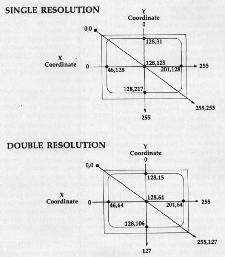
SHAPE is the address of the shape data for the player or missile. The best way to use this parameter is to specify the address of a string which contains previously created shape data. For background on designing player shapes, see Part 2 of the three-part series mentioned above. In a moment, we'll discuss a Toolkit utility that lets you design your own shapes with a joystick and which calculates the shape data for you. The SHAPE parameter, incidentally, is what allows players to flip between different shapes even while they're moving. Each time you move a player or missile, the PMMOVE subroutine erases the object's entire memory area and replaces it with the new image you select with the SHAPE parameter. If you don't quite follow this explanation, the example programs will clarify things.
SIZE is the height of the player or missile in bytes. If the shape data referred to by SHAPE consists of eight bytes, you'd insert an 8 for this parameter. This makes it possible to store the data for numerous player shapes in a single string, then select just the shape you want by pointing SHAPE to its position within the string and specifying the substring's length with SIZE. Again, the example programs will demonstrate this technique.
The final two parameters determine the new position of the player or missile on the screen. X is the horizontal coordinate and Y is the vertical coordinate. Like the screen coordinates used by BASIC graphics commands such as PLOT and DRAWTO, position 0,0 refers to the upper-left corner. As the X coordinate increases, the P/M object moves from left to right; as the Y coordinate increases, the object moves from top to bottom. X values can range from 0 to 255. Y values can range from 0 to 255 in single-resolution P/M graphics or 0 to 128 in double-resolution P/M graphics. If the X or Y values exceed these ranges, the object eventually "wraps around" to the opposite side of the screen. But if you specify an X or Y value which is less than 0, an error results.
The accompanying figure shows the layout of these coordinates. Notice how some positions are off the visible screen area. A quick way to make an object disappear is to move it to one of these "invisible" positions. (Another way is to specify 0 for the SIZE parameter.)
Frame Flipping
Now for the fun stuff. The following examples show some typical ways to use the PMMOVE statement in your own programs.
Program 2 demonstrates how to store a player shape in a string. After typing Program 2, LIST it to disk or tape, then merge it in memory with Program 1 by using the ENTER command. When you type RUN, there's a pause as everything sets up, then a player in the form of a smiling face appears in the center of the screen. Here's how it works:
Line 10 calls the Toolkit setup routine (Program 1), specifying single-resolution P/M and graphics mode 0. Line 20 dimensions the string variable SHAPES to hold 11 characters, the size of the player (11 bytes tall). Next it uses BASIC'S ADR function to set the variable SHAPE to the address of SHAPES, and sets SIZE to 11. Then it uses a FOR-NEXT loop to read the 11 bytes of shape data in line 40 into SHAPES.
Finally, the PMMOVE statement in line 30 makes the player appear at position 127,127 (the centerpoint in single-res P/M graphics). Note that the PLAYER# parameter is 1; simply by changing this number to 2, 3, or 4, you can display any of the other players using the same shape data—try it. (By the way, you should press SYSTEM RESET before rerunning this or any other program that uses player/missile graphics. Otherwise, the reserved P/M memory keeps growing until it consumes all the RAM in your computer.)
The technique of storing player shape data in strings has some interesting applications. By storing several shapes in a single string and flipping rapidly between them, you can make your players come alive as they move about the screen. Even a static player can seem to move as its shape continuously changes, much like frame animation in a cartoon. To see an example, type in Program 3. LIST it to disk or tape, then merge it in memory with Program 1 using the ENTER command. When you type RUN, the program initializes for a few seconds, then displays a small explosion in the middle of the screen, hurling fragments in all directions. Yet, throughout this animated sequence, the player object never moves.
The secret is BOOM$, a 64-character string filled with eight player shapes in line 30. Each shape is eight characters long, as seen in the DATA statements in lines 90–160. The PMMOVE statement in line 60 rapidly flips through all eight shapes in sequence because it is sandwiched within the FOR-NEXT loop between lines 40 and 80. (The loop serves double duty; it also fades the explosion sound into silence.) Another FOR-NEXT in line 70 is a simple delay loop. To slow down the explosion sequence for a better idea of what's going on, change the 35 in line 70 to a larger number—say, 150. Also notice how the final player shape in this sequence consists of nothing but zeroes. This is another way of making the player object seem to disappear without moving it off the screen.
Whirling Dervishes
Another fascinating application of this technique is to design players which change shape depending on which direction they're moving. To see an example, type in Program 4. As before, LIST the program to disk or tape, then merge it with Program 1 using ENTER.
When you type RUN, a red tank appears in the center of the screen. The low rumble of an idling engine can be heard in the background. Plug a joystick into port 1, then try moving the stick right or left. Notice how the tank rotates clockwise or counterclockwise. In fact, it spins so fast it's almost a blur.
The player isn't actually rotating or moving, of course; it's simply changing shape many times per second, thanks to the SHAPE parameter of the PMMOVE routine. The secret, again, is a string (SHAPES) which contains shape data for eight tank images, one for each of the eight possible directions. Lines 40–80 read the joystick and determine which image should be displayed.
Now push the joystick forward. The engine revs up and the tank obediently moves in the direction it is pointed. You can drive the tank all over the screen. To see how this works, study lines 90–190. Notice how the ON-GOTO statement in line 90 passes control to one of the lines from 120 to 190, depending on which direction the tank is oriented. Each of these lines either increments or decrements the X and Y coordinates to move the tank in one of the eight possible directions.
Notice, too, how this entire program contains only the one PMMOVE statement in line 80—a single statement controls both the player's shape and its movement.
Stepping On The Gas
To make the tank move twice as fast, change lines 120–190 so the X and Y coordinates are incremented or decremented by 2 instead of 1. For still more speed, you can even change these values to 3. However, keep in mind that the movement is not quite as smooth as these step values are increased; the object seems to jerk along at higher speeds. A step value of 2 or 3 is a reasonable compromise between speed and loss of grace.
Try changing the PLAYER# parameter in the PMMOVE statement to 2, 3, or 4 to see the other players in action.
For an example of missile animation, merge Program 5 with both Program 1 and Program 4. These lines let the tank fire a shot when you press the joystick button. The direction routine is very similar to the one in Program 4; in fact, it uses the same variable (DIR) to figure out which way the tank is pointing.
Note how the missile shape defined in line 25 is only one byte long—CHR$(3). Unlike player objects, which are eight bits wide, missiles are only two bits wide. You can't design a very fancy shape with only two bits to work with, so most programs use the missiles for such tiny shapes as projectiles, bullets, etc. A single byte is enough to define a missile shape for these purposes. Since all four missiles share the same memory area as a single player, defining missile shapes is a little different than defining player shapes.
Rather than getting into a confusing discussion about missiles and bit manipulation, just remember this: The shape bytes for the four missiles (accessed as PLAYER# 5, 6, 7, and 8 in the PMMOVE statement) should be 3, 12, 48, and 192, respectively. For instance, the PMMOVE statements in lines 1100 and 1110 refer to the first missile, PLAYER# 5, so its shape data in MISSILES is a 3. If you want to move the second missile, change the PLAYER# parameter to 6 and the shape byte in line 25 to CHR$(12). If you want to move the third missile, change the PLAYER# parameter to 7 and the shape byte to CHR$(48). And if you want to move the fourth missile, change the PLAYER# parameter to 8 and the shape byte to CHR$(192). These shape bytes will work with missiles in any of your own programs.
Designing Player Shapes
As a final touch, the P/M Graphics Toolkit includes a small utility for designing your own players. It's not very elaborate, but it's better than scribbling on graph paper and counting up "on" bits and "off" bits in your head.
Like the other example programs, the shape utility is based on the Toolkit setup/animation routine. To prepare it, type in Program 6 and merge it with Program 1. SAVE or CSAVE a copy of the merged program so you won't have to repeat these steps each time you want to use the utility.
After typing RUN, select single- or double-resolution player/ missile graphics by pressing 1 or 2. The utility spends a few moments initializing, then displays a grid of dots along the left side of the screen. A cursor is at the upper-left corner; it's controlled by a joystick plugged into port 1.
The grid represents a magnified view of an eight-bit-wide player strip, with one dot for each bit. Each horizontal row of eight dots, therefore, represents one byte of the player strip. Player strips are really 255 bytes tall in single resolution or 128 bytes tall in double resolution, but there isn't room to display a grid that large on the screen. Still, the grid is tall enough to design player shapes for most purposes.
To design a shape, just move the cursor anywhere on the grid and press the joystick button to set a bit. The dot changes to inverse video, and an actual-size player begins taking form in the blank area on the right side of the screen. Simultaneously, a number representing the byte value for that row of bits appears. Try moving the cursor and setting more bits; the byte values keep changing. To erase a bit that you've set, position the cursor on it and press the joystick button again. With each change, the byte values are updated along with the actual-size player.
When you're satisfied with a player shape, jot down the byte values. (You can ignore the zeroes, if any, above and below the shape.) These byte values represent the shape data for your player. To display the player in your own programs, just read the numbers into a string as demonstrated in Programs 2, 3, and 4. Use the address of this string as the SHAPE parameter in the PMMOVE statement. The number of shape bytes becomes the value for the SIZE parameter.
If you mess things up too badly when designing a player, you can erase the entire grid by pressing the E key.
This is a bare-bones utility, but it's enough to get you started and take the bothersome paperwork out of defining player shapes. If you want, you can add more features of your own—commands to change player colors; to shift bit patterns left, right, up, or down; to flip the pattern as a mirror image; to automatically generate DATA statements of player shape bytes; and so on.
A Bonus Routine
Both machine language subroutines used by the Toolkit are designed to be as crashproof as possible. If you accidentally pass the wrong number of parameters in a USR statement, the routines immediately clear all faulty values off the 6502 stack and bounce back to BASIC. So if you call the PMMOVE routine and nothing happens, check the USR statement to make sure you included all of the parameters and that the parameters have legal values.
You may find one of the Tool-kit machine language routines useful in other types of programs as well. PAGCLR is a general-purpose routine that rapidly clears a specified number of memory pages with zeroes. For P/M graphics, this routine erases any garbage data that may be cluttering the reserved memory area. But it's handy for any program that needs to clear out a large amount of memory in a split-second.
The ML data for PAGCLR can be found in the DATA statements in Program 1 at lines 20160–20240. Line 20060 reads this data into the string PAGCLR$, previously DIMensioned to 48 characters. The variable PAGCLR is set to the address of PAGCLR$.
Here's the format for calling the PAGCLR routine:
A = USR(PAGCLR,ADDRESS,PAGES)
where PAGCLR is the address of the ML routine, ADDRESS is the starting address (in decimal) of the memory area you want to clear, and PAGES is the number of memory pages to clear (a page equals 256 bytes). For example, the last statement in line 20130 clears either 1,024 or 2,048 bytes starting at the memory address PMBASE, depending on whether the variable PAGES is set to 4 or 8 for double- or single-resolution P/M graphics.
Caution: Don't use the PAGCLR routine for other purposes unless you understand exactly how it works. If misdirected, it can wipe out massive amounts of memory in an instant and crash your computer.
For Instructions on entering these listings, please refer to "COMPUTE!'s Guide to Typing In Programs" published in this issue of COMPUTE!.