Atari
Animation
With
P/M Graphics
Part 2
Robert J Powell
With
P/M Graphics
Part 2
Robert J Powell
Part 1 of this series introduced the basic concepts of Atari player/missile graphics and showed how to display all four player strips on the screen. This month, Part 2 demonstrates how to redefine players into any shapes you want and how to move them horizontally.
If you ran last month's example program, you saw the Atari's players as they really appear: four colored strips which are eight bits wide and taller than the screen. To really make use of player/missile graphics, your program must transform these featureless strips into shapes of your own design. It isn't a difficult task, though it helps if you have a grasp of binary numbering. But even if you know nothing about binary, we'll provide plenty of step-by-step examples so you can learn by experimentation.
First, run last month's program again. (For those who missed it, it's listed below as Program 1.) When the program finishes, you should see four colored strips at the right side of the screen and the READY prompt at the left. Don't press SYSTEM RESET or any other keys for now; we'll illustrate how shapes are defined by changing one of these players in direct mode so you can see the effects immediately.
If you refer to the P/M memory map in Part 1, you'll notice that the memory area for the four players extends from PMBASE+1024 to PMBASE + 2048. That's a total of 1,024 bytes, or 1K. (Remember, this program is using single-line resolution P/M graphics, so each of the four players is 256 bytes tall. If it were using double-line resolution, each player would be only 128 bytes tall, and player memory would extend from PMBASE+512 to PMBASE+1024.)
The numbers stored in this memory area determine the shape of each player. Right now, the memory area for all four players is filled with the number 255, POKEd there by line 90 of Program 1. The players appear as solid strips because 255 is the largest number which can be stored in a single byte. The key to defining a shape is to selectively display only parts of the player strip by POKEing numbers between 0 and 255 into the player's memory area.
Building A Box
Let's start by redefining the shape of player 0 (by custom, the four players are numbered 0 to 3). Referring again to the P/M memory map in Part 1, notice that player 0's memory extends from PMBASE+ 1024 to PMBASE+1280 (256 bytes). This is the target for our POKEs. In direct mode-that is, without a line number-type this line and press RETURN:
FOR X=PMBASE+1024 TO PM
BASE+1280:POKE X,0:NEXT
X
You should see the player 0 strip disappear. Why? Because this line POKES 256 zeros into the memory area for player 0, erasing the 255s previously stored there. Notice that players 1, 2, and 3 remain unaffected.
Now let's restore part of the player 0 strip to make a simple shape. One by one, enter the following lines, pressing RETURN each time:
POKE PMBASE+1152,255
POKE PMBASE+1153,129
POKE PMBASE+1154,129
POKE PMBASE+1155,129
POKE PMBASE+1156,255
Each time you press RETURN, you should see a hollow box taking shape where the player 0 strip used to be. If you examine the POKE statements, you'll notice that the first number in each statement is a memory address in the middle of the player 0 memory area. These addresses determine the shape's vertical position within the stripand therefore its vertical position on the screen.
The second number in each statement actually defines part of the box. Experiment by POKEing other numbers between 0 and 255 into these addresses (as well as other addresses in the player 0 memory area). Once you learn how these numbers are arrived at, you can create almost any shape you want.
Patterns Of Bits
The numbers between 0 and 255, when POKEd into a byte, represent bit values in the binary number system. These bit values translate directly into player shapes.
A byte contains eight bits, or positions. Each position has a different value ranging from 1 to 128. When a certain bit position in a player/missile strip is turned "on," it appears onscreen as a tiny dot. Bits which are turned "off" do not appear onscreen. To define a shape, then, you have to figure out which bits to turn on, add up the bit values of their positions, and POKE the resulting number into the appropriate memory address.
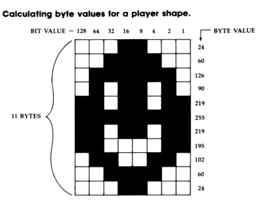
The accompanying figure makes this explanation more clear. It shows the bit pattern for a player defined as a happy face. The bit values are the numbers running across the top of the figure; notice now the values double for each bit position running from right to left.
The numbers running down the side of the figure are the byte values, or the sums of the bit values for each byte. To arrive at the byte values, you add up all the bit values for "on" bits in each row. For instance, the top row, or byte, has two bit positions turned "on": bits 8 and 16. Therefore, the byte value for that row is 8 + 16, or 24. The next byte has four bit positions turned "on": bits 4, 8, 16, and 32. Therefore, the byte value is 4 + 8 + 16 + 32, or 60. All the other byte values are determined in a similar fashion. These are the numbers you POKE into the player memory area to make the shape appear.
To see this in action, press SYSTEM RESET and run Program 1 again. When it stops, fill the player 0 memory area with zeros using the FOR-NEXT loop as we did before. Then enter these lines, pressing RETURN after each one:
POKE PMBASE+1152,24
POKE PMBASE+1153,60
POKE PMBASE+1154,126
POKE PMBASE+1155,90
POKE PMBASE+1156,219
POKE PMBASE+1157,255
POKE PMBASE+1158,219
POKE PMBASE+1159,195
POKE PMBASE+1160,102
POKE PMBASE+1161,60
POKE PMBASE+1162,24
Each time you press RETURN, another byte of the player shape should appear.
Try designing your own shape using a blank version of the grid in the figure. After coloring in each square to make the shape, add up the bit values to arrive at the numbers for your POKE statements. Remember that your shape can be only eight bits wide, but can be as tall as the screen.
Storing Player Shapes
When you're writing a program that defines player shapes, it's inconvenient to POKE the byte values into memory in direct mode, of course. Usually the byte values are stored in a DATA statement, retrieved by a READ statement within a FOR-NEXT loop, and then POKEd into memory.
To see an example, add these lines to Program 1:
XT X
100 FOR X=1 TO 11
110 READ A
120 POKE PMBASE+1152+X,A
130 NEXT X
140 DATA 24,60,126,90,219
,255,219,195,102,60,2
4
Line 90 clears out the player memory area with zeros. Lines 100-130 are the loop which READs the DATA in line 140. Notice that line 120 POKES the byte values into the middle of the player 0 memory area. To define this shape as player 1, you could simply add 256 to this address; to define it as player 2, add 512; and to define it as player 3, add 768.
Missiles are defined in a similar way, with one important difference: Because each missile is only two bits wide, all four missiles share the same amount of memory as a single player. That means the bit patterns are two-bit slices of the grid in the figure. By referring to this figure and the P/M memory map in Part 1, you can see that missile 0 is defined by adding the bit values 1 and 2; missile 1 is defined by the bit values 4 and 8; missile 2 is defined by the bit values 16 and 32; and missile 3 is defined by the bit values 64 and 128.
Of course, with only two bits to work with, missile shapes are pretty limited. That's why they're used mostly in games as "bullets" fired by player shapes.
Horizontal Animation
By now you're probably wondering how to animate the shapes you've created. We'll tackle horizontal movement first because it's the easiest; we'll save vertical animation for Part 3 next month.
In Part 1 we mentioned that each player has a horizontal position register, a memory location which determines the horizontal placement of the player on the screen. These memory locations are 52348 for player 0, 53249 for player 1, 53250 for player 2, and 53251 for player 3. Line 80 of Program 1 POKES these registers to group all four players together near the right edge of the screen. Any number from 0-255 can be POKEd into the registers, but the range of numbers which position the player on the visible part of the screen is only about 45 to 205.
Moving a player horizontally is as simple as POKEing different numbers into the appropriate position register. Add these lines to Program 1:
100 FOR X=45 TO 205
110 POKE 53248,X
120 NEXT X
When you type RUN, this loop moves player 0 across the screen from left to right. By changing the register address in line 110, you can move any of the four players.
Missiles are moved horizontally like players; the four horizontal position registers for the missiles are at memory locations 53252 to 53255. To see the missiles onscreen, add these lines to Program 1:
85 POKE 53252,140:POKE 53
253,144:POKE 53254,148
:POKE 53255,152
90 FOR X=PMBASE+768 TO PM
BASE+2048:POKE X,255:N
EXT X
One-Way Registers
There's only one tricky detail to keep in mind when manipulating the horizontal registers-they are write-only memory locations, which means they can be POKEd but do not return useful values when PEEKed. This makes your programming more complicated, because you can't keep track of a player or missile's horizontal screen position merely by PEEKing its horizontal register. Instead, you have to set aside a variable for each object to store its horizontal position. Every time the object moves, your program must update the corresponding variable.
This technique is demonstrated in Program 2. It's a modified version of Program 1 that lets you move player 1 left or right with a joystick plugged into port 1. Notice how the variable P1 keeps track of the player's horizontal position. Also notice how player 1 moves over players 2 and 3, but beneath player 0. These different display priorities let your programs simulate 3-D graphics effects.
Try modifying Program 2 yourself to move the other three players. Be careful about moving the player too far off the edges of the screen, though-if the program tries to POKE a value smaller than 0 or greater than 255 into the horizontal register, it will crash with an error.
In Part 3, we'll cover a method of vertical animation and a few other details about player/missile graphics as well.
For instructions on entering these listings,
please refer to "COMPUTEI's Guide to Typing
In Programs" published bimonthly in COMPUTE!.
Program 1: P/M Demo
MF 10 POKE 106,PEEK(106)-8
NF 20 POKE 54279,PEEK(106)
HD 30 GRAPHICS 0:SETCOLOR 2,
0,0
CN 40 PMBASE=PEEK(106)*256
ML 50 POKE 559,62
PM 60 POKE 53277,3
DP 70 POKE 704,68:POKE 705,1
98:POKE 706,168:POKE 7
07,148
PA 80 POKE 53248,160:POKE 53
249,170:POKE 53250,180
:POKE 53251,190
DM 90 FOR X=PMBASE+1024 TO P
MBASE+2048:POKE X,255:
NEXT X
Program 2: Horizontal
Animation
10 POKE 106,PEEK(106)-8
20 POKE 54279,PEEK(106)
30 GRAPHICS 0:SETCOLOR 2,
0,0
40 PMBASE=PEEK(106)*256
50 POKE 559,62
60 POKE 53277,3
70 POKE 704,68:POKE 705,1
98:POKE 706,168:POKE 7
07,148
80 POKE 53248,160:POKE 53
249,170:POKE 53250,180
:POKE 53251,190
90 FOR X=PMBASE+1024 TO P
MBASE+2048:POKE X,255:
NEXT X
100 P1=170
110 S=STICK(0)
120 IF S=7 THEN P1=P1+1:I
F P1>255 THEN P1=255
130 IF S=11 THEN P1=P1-1:
IF P1<1 THEN P1=1
131 POKE 53249,P1
140 GOTO 110