Working With SID
Jerry M. Jaco
In this unique approach to the Commodore 64's SID chip, the author discusses the SID chip's anatomy and capabilities in the context of its essential similarity to the design of musk synthesizers.
If you've decided you want to make music on your Commodore 64, and you've read all the literature on the subject and still don't know where to begin, perhaps a look at how an analog synthesizer is used in an electronic music studio will clarify many aspects of the 64's amazing sound capabilities. Once we have covered the physical aspects of a synthesizer, we can begin to understand some of the techniques used to create sounds artificially.
Electronic music studios usually include at least one analog synthesizer. Most synthesizers have a modular design which allows the synthesizer to be built and expanded according to the dictates of budget, space, and ability. Each module on the synthesizer has a different function, and the builder-user is free to duplicate or omit these functions in any way he sees fit.
Each module on the synthesizer is independent of all the others. The only way to connect them is either by a panel of fancy selector switches or via the more common patch cords. Patch cords are simply pieces of electrical cable of varying lengths which have standard plugs attached on each end. Plugging one end of a patch cord into the output socket of one module and the other end of the patch cord into the input socket of another module creates an electrical pathway called a patch.
If a patch leads from a Source module, such as an oscillator, to an Output module, such as a mixer, the resulting sound will be audible to the outside world. (See Figure 1.) The term signal is used to describe the electrical current being passed from one module to another. A source signal is one that will eventually be heard as a real sound. A control signal is a varying voltage used to electronically control another module. It does not contain sound information per se.
A "Patch" For The SID Chip
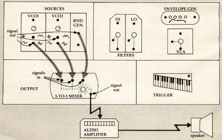
In Figure 1, there is only one source signal being processed by the mixer. A mixer can handle up to three source signals on our hypothetical system, which it combines into one composite signal that gets sent on to the speakers, and to your ears. (See Figure 2.) On the 64, Program 1 accomplishes exactly what the analog synthesizer does in Figure 2.
Program 1: Three Voices—Or A Chord
10 FOR I = 0 TO 24 : POKE 54272 + I, 0 : NEXT
20 POKE 54272, 37 : POKE 54273, 17 : REM OSC1
30 POKE 54279, 229 : POKE 54280, 22 : REM OSC2
40 POKE 54286, 214 : POKE 54287, 28 : REM OSC3
50 POKE 54276, 17 : POKE 54283, 17 : POKE 54290, 17 : REM TRIANGLE WAVE FOR ALL OSC'S
60 POKE 54278, 245 : POKE 54285, 245 : POKE 54292, 245 : REM SUS / REL VALUES FOR ALL OSC'S
70 POKE 54296, 15 : REM MASTER VOLUME ON
75 FOR T = 1 TO 500 : NEXT : REM CHORD DURATION
80 POKE 54276, 16 : POKE 54283, 16 : POKE 54290, 16
90 FORT = 1 TO 250 : NEXT : REM RELEASE DURATION
95 POKE 54296, 0 : REM TURN OFF VOLUME : rem 29
96 END
This is a very basic "patch" for the Sound Interface Device (SID) chip on the 64. Lines 20, 30, and 40 set the frequencies of the three oscillators. Line 20 POKEs the values for middle C into Voice 1. Line 30 POKEs the values for F into Voice 2, and line 40 POKEs the values for A into Voice 3. This gives us a "chord," which is simply three notes (voices) sounding simultaneously. Line 50 selects a triangle wave output for all three voices. Line 70 is the mixer volume control. When the value 15 is POKEd into this location, the master volume control is turned all the way up. When 0 is POKEd, the volume control is turned off, as in line 55. The other lines will become clearer as we go along.
Figure 1: Processing A Single Source Signal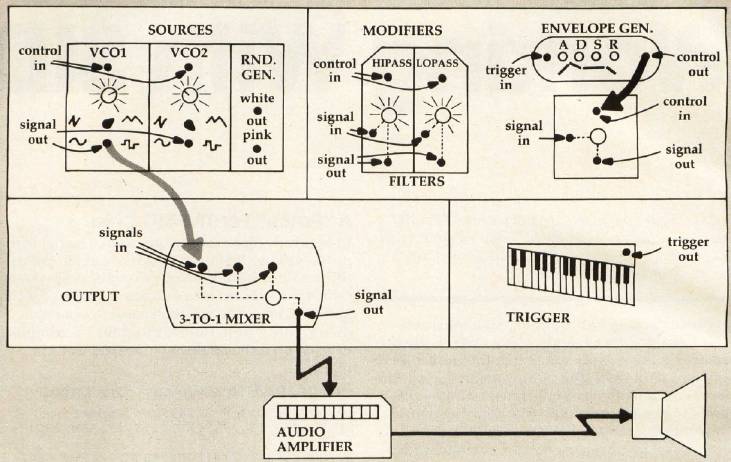
On an analog synthesizer, pots (potentiometers) are controls that do things such as raise and lower the volume of a sound signal or change the frequency (pitch) of an oscillator. Pots are also the main components of game paddles and TV volume controls. To make new sounds on an analog synthesizer, the user will twist pots on each module and listen for the resulting effect. When he finds one he likes, he either records the sound on tape or writes down the patch on a patch chart, marking the pathways made by the patch cords and the positions of the pots for future reference. Analog synthesizers are very useful in this way because drastic changes in a sound can be quickly made by simply twisting a knob or plugging a patch cord into something else.
Turning Knobs With POKEs
A digitally-controlled synthesizer, such as our SID chip, uses numbers POKEd into control registers to accomplish the same things that knobtwisting and patch-cord-plugging do on an analog synthesizer. For example, if you POKE a 16-bit value into the first two registers of the SID chip (54272 and 54273), you've set the frequency value for Oscillator 1. POKE a four-bit number into the high nybble of the sixth register on the chip, and you've set the Attack value of the envelope for Oscillator 1. POKEing different values into other registers will activate them in the same way that turning the pots or setting switches will activate the analog synthesizer modules.
Envelope Generation
Look at Figure 1 again. It shows a direct path from an oscillator (VCO1) to the mixer. If we were to break that path, sending the output of VCO1 to the input of the amplifier module (VCA), we would then need to send the output of VCA to the mixer so that the sound from VC01 could still be heard. The patch shown in Figure 3 would be the result. Now we can make VCOl's signal even louder by adjusting the pot on VCA or on the mixer. The real reason for taking this route is that the envelope generator can be brought into play, since it directly controls the VCA.
There are four pots on the envelope generator module. The first controls the Attack time; the second, the Decay time. The third sets the Sustain level, and the fourth controls the Release time. On the SID, two registers in high-low nybble format control these functions. The most important function is perhaps the Sustain level. It is not a timing value, but is rather the level at which the amplifier's volume control is set while the note is being sounded. If the Sustain level is zero, no sound will be heard after the Attack and Decay phases have ended.
The envelope generator puts out an electrical signal which tells the amplifier when to turn up the volume and how long it should take, as well as how high to set the volume, and when and how long to turn it all the way off again. This is why the amplifier module in the diagrams is called "VCA." This stands for Voltage Controlled Amplifier and means that the amplifier can be controlled by an incoming variable voltage, such as the one supplied by the envelope generator.
Figure 3: Using The VCA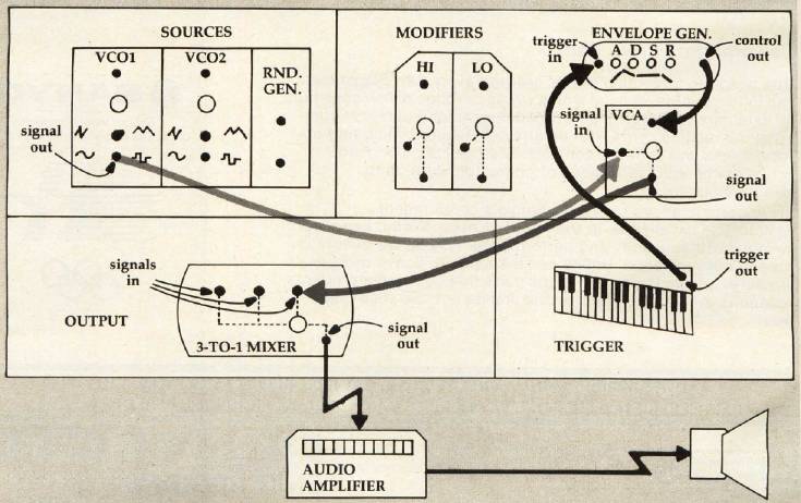
ADSR Values
On the SID chip, each voice has its own envelope generator. Within the group of seven registers (0–6) that control the three oscillators, register 5 contains the Attack and Decay values in high-low nybble format, and register 6 contains the Sustain/Release values. All values are four-bit numbers (nybbles). The Attack value determines how long the amplifier should take to reach peak amplitude (maximum volume).
The Decay value determines how long the amplifier should take to go from peak amplitude to the level specified by the Sustain value. The Release value is the time the amplifier will use to return to the lowest amplitude level ("off") from the Sustain level.
Remember, though, that on the analog synthesizer as well as on the SID chip, the envelope will not go into effect until it is "triggered." The lowest order bit (bit 0), the Gate bit, triggers each envelope on the SID chip. On the analog synthesizer, triggering of the envelope is accomplished through the use of an attached keyboard module. When a key is pushed down (and as long as it is held down), the Attack, Decay, and Sustain values will go into effect in order. When the key is released, the Release phase is triggered, and the VCA will close down the volume of the signal it is operating on over the length of time specified by the Release value.
Program 2 demonstrates the effect of the various ADSR values:
Program 2: Effects Of The ADSR Values
100 FOR I = 0 TO 24 : POKE 54272 + I, 0 : NEXT
110 POKE 54272, 37 : POKE 54273, 17 : REM OSC 1
120 POKE 54276, 129 : REM NOISE WAVE OSC 1
130 POKE 54277, 240 : REM SLOW ATTACK / FASTEST DECAY RATE
140 POKE 54278, 240 : REM HIGHEST SUSTAIN LEVEL / FASTEST RELEASE RATE
150 POKE 54296, 15 : REM FULL VOL. AT MIXER
160 FORT = 1 TO 4500 : NEXT : REM DURATION FOR ATTACK, DECAY, AND SUSTAIN
170 POKE 54276, 128 : REM BEGIN RELEASE CYCLE
180 FORT = 1 TO 4500 : NEXT : REM REL. DURATION
190 POKE 54296, 0 : REM TURN OFF VOLUME
191 END
In line 130, the Attack value is all the way on, and the Decay value is all the way off. In line 140, the Sustain value is all the way on and the Release value is off. Each value is a four-bit number, 0 to 15. With the Attack and Sustain setting, the actual POKE value is shifted to the high nybble; thus, 240 is actually the Attack value equal to 15 (for slowest Attack) multiplied by 16. The sound generated is a random noise that gradually gets louder and then stops suddenly. It stops suddenly because we have set the Release value to 0, allowing no time for a gradual decrease in volume.
Change the value 240 in line 140 to 255 and RUN the program again. The sound should slowly fade away. The high nybble of 54278 (Sustain) is now 240 and the low nybble (Release) 15, making a total of 255, the value we just PoKEd into 54278. Try lowering the Sustain value by two or three (2 * 16 or 3 * 16); that is, POKE 54278 with either 223 or 207 and see what happens. The sound should build up as before but should then fall off markedly. Change the Decay value from 0 in line 130 to about 8 (POKE 54277,248) and hear how the drop-off is now smoothed out. Similarly, shorten the Attack time to vary the start of the sound the same way the Sustain value was altered. The results should be vastly different from those we started with, and we've been working with only two registers!
Look now at line 170. Notice that we subtracted one from the value we originally POKEd into 54276 in line 120. This zeros the Gate bit in 54276, and it is the same as taking your finger off the keyboard on the analog synthesizer: the Release cycle gets triggered. Of course, it works only if the VCA Sustain level has been previously raised high enough to hear the tone. The delay loop in line 180 is also necessary to allow the Release cycle to reach its lowest level.
Using Filters To Color Sound
Let's add a filter to the path in Figure 3. The path from the VCA to the mixer is broken so that filtering the modulated signal will be more easily heard. In our diagram, we have a choice of a high-pass or low-pass filter. On the SID chip, we can also utilize a Band-Pass filter.
The pot on each filter is used to adjust the cutoff frequency, which is the frequency above which a high-pass filter allows frequencies in the sound spectrum to be heard and below which the filter suppresses them. The low-pass filter is the opposite of the high-pass filter in that it suppresses the frequencies above the cutoff value and allows those below it to sound. A Band-Pass filter allows frequencies to be heard within a narrow band surrounding the cutoff frequency (called a center frequency in this case), while suppressing all the rest. Use of filters constitutes a technique called subtractive synthesis, which selectively eliminates available frequencies of the sound spectrum, producing widely varying sound colors.
Figure 4: Using A High-Pass Fitter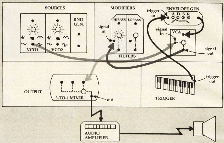
Figure 4 indicates that we've decided to filter VCO1 through a high-pass filter. VCO1 is set to produce a sawtooth wave. The path of the patch runs out of VCO1 into the VCA, and from the VCA into the HIPASS filter. From there, the signal heads to the mixer and out to the speaker. Program 3 is a routine that does the same thing.
Program 3: Filtered Sound
200 FOR I = 0 TO 24 : POKE 54272 + I, 0 : NEXT
210 POKE 54272, 37 : POKE 54273, 17 : REM OSC1
220 POKE 54276, 33 : REM SAWTOOTH WAVE OSC1
230 POKE 54277, 120 : REM MED. ATTACK / MED. DECAY
240 POKE 54278, 245 : REM HIGHEST SUSTAIN / MED . RELEASE
245 POKE 54293, 40 : POKE 54294, 5 : REM CUTOFF FREQUENCY FOR HIGH-PASS FILTER
250 POKE 54295, 129 : REM MED RES'NCE AND OSC1 TO BE FILTERED
255 POKE 54296, 79 : REM FULL VOL. AND CHOOSE HIGH-PASS FILTER
260 FOR J = 1 TO 250 : POKE 54294, J : NEXT : REM SWEEP CUTOFF FREQ. UPWARDS
270 POKE 54276, 32 : REM BEGIN RELEASE CYCLE
280 FORT = 1 TO 500 : NEXT : REM REL. DURATION
290 POKE 54296, 0 : REM TURN OFF VOLUME
295 END
To hear the effect of the filter, in line 260 we will sweep the value of the cutoff frequency from low to high. This will allow less and less of the available sound spectrum to be passed by the filter. Listen carefully to the richness of the tone as it is diminished. Switch the wave form to Noise in line 220 by POKEing 129, instead of 33, into 54276 to hear a different version of the effect. Many effects are possible using filters.
Frequency Modulation
Figure 5 introduces another technique called Frequency Modulation. Notice now that the signal from VCO1 is entering the control input of VCO2, and that the signal from VCO2 is going through the VCA and on to the mixer. The frequency of VCO2 is now being controlled automatically by the output voltage of VCO1 instead of manually by the pot. This is another example of voltage control. The envelope generator controlled the VCA before and an oscillator now controls a VCO (Voltage-Controlled Oscillator).
Frequency Modulation (FM), along with filtering and envelope control, is one of the most significant techniques of sound synthesis. Using one signal source to alter the sound quality of another provides incredibly powerful and varied tools for sound manipulation. Program 4 is one simple example of the FM technique.
Figure 5: Frequency Modulation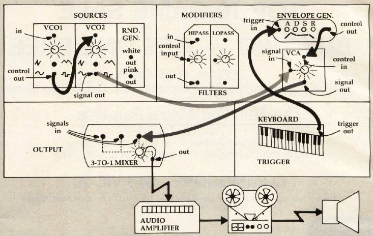
Program 4: siren
300 FOR I = 0 TO 24 : POKE 54272 + I,  0 : NEXT
310 POKE 54276, 33 : REM SAWTOOTH WAVE OSC1
320 POKE 54286, 3 : REM CONTROL FREQ. OSC3
330 POKE 54290, 16 : REM TRIANGLE WAVE 0SC3
340 POKE 54296, 175 : REM FULL VOL. & SELECT B AND-PASS & DISC. OSC3 FROM AUDIO
350 POKE 54295, 1 : REM NO RES'NCE & CHOOSE OSCI FOR FILTER
360 POKE 54293, 255 : POKE 54294, 78 : REM CUTOFF FREQUENCY
370 POKE 54278, 240 : REM FULL SUSTAIN/FASTEST RELEASE RATE
375 FOR T = 1 TO 300
380 F = 20000 + PEEK (54299) * 20 : REM ADD OSC3 OUTPUT TO BASE FREQUENCY
390 HF = INT (F/256) : LF = F-256 * HF : REM SPLIT NEW FREQUENCY INTO HIGH/LOW BYTES
400 POKE 54272, LF : POKE 54273, HF : REM SET NEWOSCI FREQUENCY
410 NEXT : POKE 54276, 32 : POKE 54296, 0
420 END
The third oscillator on the SID chip is our control oscillator, as VCO1 is in Figure 5. We get access to a value corresponding to the wave shape of Oscillator 3 in register 27 (54299). If Oscillator 3 is set to a triangle wave, the values in register 27 will go up from 0 to 255 and then down from 255 to 0 in a symmetrical rhythm.
This is a nice shape for a siren sound, which is what Program 4 creates. Notice that the frequency of Oscillator 3 in line 520 is very low. This value allows the tracing of the waveform to be heard as a siren. The range of frequencies under approximately 32Hz is called the sub-audio range and refers to the fact that the actual waveform at these frequencies is discernible as individual pulses instead of as a continuous tone. When Oscillator 3's frequency is increased into the audio range (above about 29), the quality of the resulting tone becomes enjoyably less predictable.
Try POKEing 220 into 54286 at line 320 and running the routine. Note how the information in register 27 (54299) is utilized in line 380. It is increased by a factor of 20 and then added to the base frequency of 20000. Program 4 also uses a Band Pass filter, but for no particular reason other than simply to stick one in. Try a different value for the waveform in line 330. If you use 64 as your value, be sure to add a line to set Oscillator 3's pulse width.
The techniques of sound manipulation described above as used with an analog synthesizer have perhaps given you a better picture of the workings of the SID chip. As you learn more about the internal registers which control other functions, you will discover others just as interesting as those discussed here.
Get a copy of the Commodore 64 Programmer's Reference Guide and read about Ring Modulation, Filtering, and other advanced techniques. Sound effects are the most directly useful sound patches to work with at the start. Program 5 is an example of one I used for a Hangman program: it's the sound of nails being driven into wood. Imagine the other sound effects you can create for new game ideas.
The User's Guide and Programmer's Reference Guide have suggested patches for you to try out. Put some FOR.. NEXT loops in, as we did in line 260 of Program 3, to have the computer, in effect, "adjust the pots" for you, as it alters individual registers. Once you've found a patch you like, save the register values for future reference. As you become more acquainted with the ways that sounds can be altered, you will find yourself noticing the subtler shades of sound color. You'll also begin to really know how the sounds on a TV commercial, videogame, or science fiction movie are created.
Program 5: Driving Nails Into Wood
700 FOR I = 0 TO 24 : POKE 54272 + I, 0 : NEXT
710 CT = 0
720 POKE 54278, 5 : REM SUSTAIN/RELEASE
730 POKE 54277, 5 : REM ATTACK/DECAY
740 POKE 54276, 129 : REM NOISE WAVEFORM
750 POKE 54295, 241 : REM RES'NCE & VOICE
760 POKE 54293, 54 : POKE 54294, 28 : REM CUTOFF
770 READA : REM INPUT HI BYTE FREQ. VALUE
780 READB : REM INPUT LO BYTE FREQ. VALUE
790 IFB = -1 THEN 900 : REM BRANCH ON END-OF-DATA
800 POKE 54273, A : POKE 54272, B : REM SET FREQ
810 FORT = 1 TO 35 : POKE 54296, 79 : NEXT : REM TURN ON VOLUME & FILTER
820 POKE 54276, 128 : REM RELEASE CYCLE
830 GOTO 730 : REM GET NEW NOTE
840 DATA 17, 37, 19, 63, 21, 154, 22, 227, 25, 177, 28, 214, 32, 94, 34, 175, 34, 255
845 DATA-1, -1
900 CT = CT + 1 : IFCT + 1 < 6 THENREST0RE : FORT = 1 TO 1 00 * CT : NEXT : GOTO 770
910 POKE 54296, 0 : REM TURN OFF VOLUME