VIC Bitmapping
C. D. Lane
If you don't think that there's enough space in an unexpanded VIC to create exciting, high resolution graphics, you're in for a surprise.
Bitmapping, controlling each tiny dot on the TV screen, is the only way to gain total control over the video image. The finest, sharpest graphics result when you govern each point of light separately.
This article deals exclusively with BASIC programming and contains a ready-to-run demo program along with an engaging, high-resolution, two-player game called "Lines." Nevertheless, some of the concepts here might be new to the beginning VIC user so we've provided a brief dictionary of the more complicated terms.
Bitmapping allows us to turn any bit on the screen on or off, usually under the control of a program. Bitmapping the VIC's screen requires software routines to plot the bits, proper initialization of the video registers, and most of RAM to store the screen.
Sizes And Shapes
The video chip in the VIC-20 computer cannot address expansion RAM. This limitation leaves it IK of RAM starting at address 0, 4K of RAM starting at 4096 ($1000 hex), 4K of ROM starting at 32768 ($8000), and IK of nybble RAM starting at 37888 ($9400). The normal state of a 5K unexpanded VIC has the character memory in the 4K of ROM, the screen memory in 506 bytes of RAM at 7680 ($lE00), and the color memory in 506 bytes of nybble RAM at 38400 ($9600). (Nybble just means that items are stored in four-bit large spaces in memory, rather than the normal, eight-bit groups called bytes.)
There are two character sizes on the VIC 6560 video chip, 8 bits by 8 bits and 16 bits by 8 bits. The 8×8 characters are the norm, and the character ROM is set up to use these. The 16 × 8 characters are twice as tall, and are useful in bitmapping the screen since they double the graphic area using the same amount of screen memory. The 8×8 characters are advantageous when using shapes from the character ROM, and they are simpler to initialize and plot.
At most, 256 different characters of 64 bits each, or 16,384 bits, can be addressed with 8 × 8 characters. To get more screen area you must use 16×8 characters. With the larger characters, 256 characters of 128 bits – or 32,768 bits maximum, twice as many – can be addressed. The 16x8 characters can be selected by turning on the low bit of 36867 ($9003). (You can turn this bit on by POKEing it with any odd number.)
The screen can also be bitmapped in multicolor mode. Multicolor mode is covered in detail in the VIC-20 Programmer's Reference Guide. Multicolor mode reduces horizontal resolution to half of normal, so the characters are now 8×4 and 16×4, using two bits for each pixel on the screen. Pixels are located in a byte by using powers of 4, rather than the powers of 2 used in high resolution mode.
Usually you will need to reshape the screen for your graphic program, since you will probably be using less area than the normal screen. Memory location 36866 ($9002) controls the number of columns on the screen, and 36867 ($9003) controls the number of rows, as well as the double high characters. Be careful of the meaning of rows when using the larger characters since rows become twice as tall.
You can format the screen by using the combination of columns and rows, which results in the closest thing to a square shape, or a combination that uses all of the RAM available. An alternate scheme is to try to do both. The standard VIC screen uses this combination: with 22 columns by 23 rows, it achieves the "most square" screen possible, using as many of the 512 characters as it can (leaving only 6 characters unused).
Where It All Goes
When you're bitmapping the screen from BASIC, there is quite a lot to fit into a small space: the screen, character, and BASIC memories all must go into the 4K of RAM at address 4096 (except, of course, in an expanded VIC, where BASIC can be moved out of internal memory). There are several ways we can accommodate BASIC and character memories, all with the screen at address 7680. In the table below, the first column is the value to POKE into the character pointer register of the VIC chip; 52,56 are the high bytes of the end of RAM pointers.
| Usable RAM | # of Chars | Screen Shape | |||||||
| 36869 | Start | 52,56 | Graphic | BASIC | 8×8 | 16×8 | Square | ||
| Maximum | 252 | 4096 | 16 | 3.5K | none | 256 | 224 | 21×21 | 16×28 |
| 253 | 5120 | 20 | 2.5K | 1K | 256 | 160 | 17×18 | 16×20 | |
| 254 | 6144 | 24 | 1.5K | 2K | 192 | 96 | 13×14 | 12×16 | |
| 255 | 7168 | 28 | 0.5K | 3K | 64 | 32 | 8×8 | 8×8 |
Moving the screen memory from 7680 to the top of the lower 1K of memory — for example, 768 ($0300), where the tape buffers are — adds 64 8×8 or 16 16×8 characters to the above figures (and adds 0.5K to the available RAM figures). However, this move is more safely accomplished via machine language. The character pointer can also be pointed at the first 1K of RAM (POKE 36869,248), but this is not very useful since page zero is used in both BASIC and machine language programming.
The case where the character pointer equals 255 is described in detail in the Reference Guide. This arrangement gives the user very little graphic area, but does allow mixing graphic characters with a subset of the ROM characters.
Programming The Bitmap
The first step in bitmapping the screen is to allocate RAM for the character memory in an area outlined in the chart. We must keep BASIC from using this memory by POKEing locations 52 and 56 with the high byte of the starting location we have chosen, and POKEing locations 51 and 55 with the low byte (which is zero for the examples in this article since they all begin on a page boundary).
To initialize the character memory, clear it by POKEing each byte with a zero. Next, initialize the screen memory by sequentially numbering the locations and POKEing each byte with its distance (in bytes) from the start of screen memory.
Program 1: Polargraph
10 POKE55,0:POKE52, 20:POKE56, 20:CLR:V=368 64:M=5120:H=248:W=7680:R=38400:K=63:S$="N"
20 U=2/3:T=l:F=0:Q=63:B=.01:L=l:C=2:FORI= .TO7:T%(7-I)=2ˆI:NEXT:POKEV+1,37:POKEV+3,32
30 PRINTCHR$(147)TAB(6)"POLARGRAPH"CHR$(17):INPUT"FREQUENCY";F
40 INPUT"OBJECT COLOR 1–8";C:IFC>8ORC<1GOTO40
50 INPUT"SCREEN COLOR 1–8";T:IFT>8ORT<1GOTO50
60 INPUT"SIZE 0-63";Q:IFQAND192GOTO60
70 INPUT"ECCENTRICITY <=1";U:IFABS(U)>1GOTO70
80 INPUT"RESOLUTION";B:INPUT"CYCLES";L:INPUT"SOLID Y/N";S$:PRINTCHR$(17)"PLEASE WAIT";
90 FORI=MTOW–512:POKEI,.:NEXT:POKEV+5,253 :POKEV,11:POKEV+2,144:G=S$ <>"Y"
100 POKEV+15,17*T–9:FORI=.TO255:POKEW+I,I: POKER+I,C–l:NEXT:FORI=.TOL*2_*STEPB
110 S = ABS(COS(F * I) * Q) : X = COS(I) * S * U + K : Y =
         SIN(I) * S + K : GOSUB160 : IFGGOTO150
120 IFABS (X-K) > ABS (Y-K) GOTO140
130 S = SGN (K-Y) : E = (K-X) / (K-Y) * S : X = X - E : FORY =
       YTOKSTEPS : X = X + E : GOSUB160 : NEXT : GOT O150
140 IFX <> KTHENS = SGN (K-X) : E = (K-Y) / (K-X) * S : Y =
       Y-E : FORX = XTOKSTEPS : Y = Y + E : GOSUB16 0 : NEXT
150 NEXT : WAIT198, 1 : GETA$ : POKEV + 5, 240 : POKEV +15, 24 :
       POKEV, 5 : POKEV + 2, 150 : GOTO30
160 Z = (YANDH) * 15 + Y + (XANDH) + M : POKEZ, PEEK (Z) ORT%
      (XAND7) : RETURN
Program 2: Lines
10 POKE52, 20 : POKE56, 20 : CLR : V = 36864 : M = 5120 :
        S = 7680 : C = 38400 : Q = 8160 : W = 240 : GOTO 80
20 I = 1 - I : FORY = .TO6STEP2 : X = Y + I * 8 :
      POKEQ + 1, H% (X) : SYS(Q) : IFPEEK (Q + 19) = H% (X + 1)THENX = Y : Y=W
30 NEXT : POKEV + 13, W : IFY > WTHENP% (I, .) = (X = 4)
      - (X = .) : P%(I, 1) = (X = 2) - (X = 6)
40 X = P% (I, 2) + P% (I, .) : Y = P% (I, 3) + P% (I, 1) :
      POKEV + 13, . : IFX > 63ORY > 159ORX * Y < . GOTO 70
50 P% (I, 2) = X : P% (I, 3) = Y : Y = (YANDW) * 15 + Y +
       (X * 4ANDW) + M : X = T% (XAND3) : IFPEEK(Y) AND XGOTO 70
60 POKEY, XORI * X * 2ORPEEK (Y) : GOTO20 :
        DATA60, 60, 62, 62, 60, 62, 56, 60, 32, 32, , 48, 32, 48, 48, 32
70 POKEV + 15 - I, 17 - I : FORI = .TOM : NEXT : GOTO110 :
      DATA 138, 96, 110, 1, 114, 142, 2, 114, 110, 212, , 65
80 POKEV + 1, 30 : POKEV + 3, 21 : POKEV, 11 : POKEV + 2, 144 :
       POKEV + 5, 253 : DIMP% (1, 3), H% (15), T% (3)
90 FORI = .TO255 : POKES + I, I : POKEC + I, 8 : NEXT : DEFFNR (X)
      = INT (RND (1) * X) : FORI = .TO3 : T% (3 - I) = 4 ˆ I
100 NEXT : FORI =.TO15 : READX : H% (I) = X + 191 : NEXT :
      FORI = .TOll : READX : POKEI + Q, X + 31 : NEXT
110 FORI = MTOS : POKEI, . : NEXT : POKEV + 15, 19 + FNR (5) :
       POKEV + 14, 16 * FNR (5) + 63
120 FORI = .TO1 : P% (I, .) = . : P% (I, 1) = FNR (2) * 2 - 1 :
       P% (I, 2) = 21 * (I + 1) : P% (I, 3) = 80 : NEXT : I = 1 : GOTO20
To plot, we will use cartesian (X, Y) coordinates, where Y is zero at the top of the screen and X is zero at the left of the screen, making the HOME position the origin (0,0). Both are bounded on the high end by the particular height and width chosen for the screen in bits. To plot a particular bit in memory from its X,Y coordinates, we must determine the actual character it resides in — which byte of that character, and which bit of that byte.
To determine what character the bit is in, drop the low order digits of the coordinates, where the number of low order digits equals log base 2 (dimension in pixels of the character). Next find the number of the character by multiplying the character's Y coordinate by the number of X characters in each row and add in the character's X coordinate. The low order Y bits not used earlier are the number of the byte in the character the bit is in. 128/ (2 to the low order X bits) locates the bit in the byte.
For example, in a 16 × 16 character screen with 8 × 8 characters, use INT(coordinate/8)*8 or simply (coordinate AND (255 - 7)) to get the character coordinates (but don't throw away the original values!). The location of the character is X + Y * 16 (the number of columns).
Location of byte in memory =
  Start of character memory
  + Number of character the byte is in * Number of bytes in character
  + The low order Y bits (the byte in the character)
To set a bit, POKE byte, PEEK(byte) OR 128/(2 ↑ low order X bits)
To clear a bit, POKE byte, PEEK(byte) AND NOT 128/(2 ↑ low order X bits)
To plot bits faster, store the powers of 2 (or 4 for multicolor mode) in an array at initialization time, saving the time of computing the powers each time.
Two programs are included here to illustrate bitmapping the screen.
Polargraph
Polargraph (Program 1) prompts the user for various parameters and uses these to draw spiral curves and solid objects. The program uses polar coordinates and the SIN() function to calculate the shapes, translates these to cartesian coordinates and plots them on the VIC's linear memory in high resolution mode. Polargraph asks for the following parameters to control plotting:
Frequency? This controls the number of "leaves" on the design; higher numbers give more leaves. It also controls overlapping — whole numbers give non-overlapping "leaves" and rational numbers give more complex patterns. As the frequency decreases from 1 to 0, different types of cardioids are produced, degenerating into spirals, and eventually ending in a perfect circle at zero, the default value. Any value is legal for this parameter.
Object color? Screen color? The number the user enters is the number on the key that the color he wishes is on; black = 1, white = 2, and so on. Numbers from 1 to 8 are legal here. The default is a white object on a black screen.
Size? This controls how far out from the center the object extends. A value around zero will make a dot in the center of the screen, and a value of 63 (half the width in bits of the screen) will make the largest possible shape. The default value here is 63.
Eccentricity? This controls how elliptical the shape is. The default 2/3 produces the most symmetric result on the screen. The default is less than 1 since the VIC's screen is not square (it uses rectangular pixels). A value of 1 (circular) is best when sending the shapes to a printer. The shapes can be stretched both horizontally or vertically. Legal values are between -1 and 1.
Resolution? This controls how many dots are used to draw the figure. A high resolution makes a finer drawing, but takes longer to draw. A low resolution draws faster with less precision. The default is .01, any value is legal, and the usable range is .5 to .001.
Cycles? This is the number of times around the graph the program runs. Its setting is related to the frequency. A simple whole number frequency requires only 1 cycle. A frequency of 3.33 requires 3 cycles to complete the drawing; 1.25 requires 2; 2.125 requires 4, and so forth. The default is 1 cycle; any value is legal. This parameter can be used to force partial drawings, open curves, incomplete spirals, etc.
Solid? This parameter controls whether the shape is drawn with dots or lines. Lines make sense only with whole number frequencies. Line mode is slower. The default is "N" which is dot mode. Legal values are "Y" and "N" (yes and no).
The user does not have to enter every parameter; just RETURNing uses the defaults outlined above. Once a drawing is complete, typing any key will get it back to the parameter menu. The defaults become the values entered on the last run, so you can just change one or more parameters to see their effect while holding others constant.
Polargraph uses a 16 row by 16 column screen in 8 by 8 character format (256 characters), simplifying the mathematics of plotting due to the symmetry of the screen. The LINES program formats the screen in a more complex and less symmetric fashion.
The designs produced by Polargraph can be printed on the VIC 1515 (or other) printer with the routine in my article "Printing the Screen" in COMPUTE!'s First Book of VIC (COMPUTE! Books, 1982). You will need to remove the IF statement after the colon on the end of line 5 if you are using more than 64 graphic characters (as Polargraph does). The variables HIGH and WIDE will also need to be adjusted to the dimensions (in characters) of the screen you are using. These changes will allow the printing of any large graphic screen.
The Lines Game
"Lines" (Program 2) is a two-player game in which each player independently guides his own line from the keyboard. The screen is formatted in double high character mode, with 16 columns by 10 rows (the equivalent of 20 rows in regular character format). The program makes the maximum use of the RAM available with BASIC and the screen in the same 4K. The screen is in multicolor mode with the two players' lines controlled by different color registers, so that they can run alongside each other without color interference, making for slightly more complicated plotting, but greater visual effect.
Each player controls a constantly growing colored line on the screen; he must not touch the walls, the other player's line, or his own line, or else his line disappears. The left line is controlled by keys A (left), D (right), W (up), and X (down). The right line is controlled by keys K (left), ; (semicolon, right), O (up), and . (period, down). The two players do not interfere with each other's control even though they both use the same keyboard.
The technique used to poll the keyboard is described in detail by Mike Bassman and Salomon Lederman in COMPUTE!'s First Book of VIC. The machine language subroutine in LINES has been moved into unused screen memory, in order to keep character memory free. It's easier to use the game if the keys that control the lines are marked with paper sticker arrows.
Both programs are as compact as possible in order to be fast and not exceed the 1K limit to program and variable space imposed by the large screen. Both programs are for an unexpanded VIC; however, they will also run with a 3K expander, all 3K of which is available for extra code.
Bitmapping the screen requires careful accounting of memory usage and small, efficient programs in an unexpanded VIC. With a little extra thought and work, it is possible to produce dazzling graphic displays and games without special hardware or software additions.
|
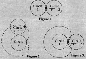
Brief Definitions Dan Carmichael, Assistant Editor Some of the terms used in this article might be unfamiliar. Here's a short description of the main ideas: • Bitmapping. Bitmapping is a process whereby each tiny individual dot (pixel) on a TV screen or monitor is represented by its own "bit" in memory. When the corresponding memory bit is zero (off), the dot (or pixel) is off. When the bit is a one (on), the pixel is turned on. Each byte of memory (an address like 1525) is made up of eight bits. When bitmapping the VIC-20, there are 32,384 separately programmable pixels. With each pixel assigned to one bit (or eight pixels to the byte), it would take 4048 bytes to bitmap the entire screen. • Cardioids. A cardioid is a heart-shaped, closed curve that is produced by tracing a fixed point on one circle as it is rolled around the circumference of another equal, stationary circle. Refer to figures 1 through 3. As circle 2 is rolled around the circumference of stationary circle 1 (Figures 1 and 2), the fixed point "P" on circle 2 begins to ???rotate and produce the heart-shaped cardioid curve. Figure 3 represents one complete revolution around fixed circle 1 and displays the completed, closed cardioid curve. Cardioid curves are used in geometric applications for the classical problem of trisecting an angle. In "Bitmapping The Screen," various types of cardioids are produced in the Polargraph program.
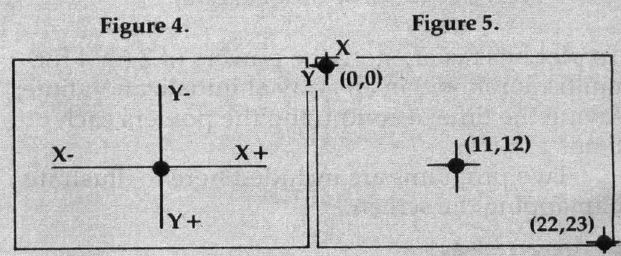
• Cartesian Coordinates. The Cartesian Coordinate system is the common x - y coordinate system that is widely used in plotting charts and graphs. The x coordinate represents an imaginary horizontal plane, the y a vertical plane (refer to Figure 4). Positions are plotted by indicating their x and y coordinates (x,y). That is, you can locate anything by giving a horizontal and vertical number. It's like the way you can locate a particular street on a city map by looking for it within the square called "F-5" or "C-2." In the article "VIC Bitmapping," x coordinate points begin at the left of the screen, y coordinate points begin at the top of the screen (see Figure 5). Coordinate 0,0 thereby becomes what computerists call the HOME position, the upper left corner of the screen. Screen positions are plotted by raising or lowering the x and y coordinates. Figure 5 illustrates plotted examples where the x,y coordinates are 11,12 (middle of the screen), and 22,23 (lower righthand corner).
Cartesian Coordinates On The TV Screen • Low Byte - High Byte. For a complete definition of low byte - high byte (LBHB) addressing techniques refer to An Explanation of LBHB in "All About USR" in this issue. • Screen Memory. Screen memory is the memory in the VIC that retains the image of what is displayed on the screen. Screen memory is RAM, and its contents are defined by the user. POKEing values into the screen memory will, in effect, display characters on the screen. • Polling The Keyboard. "Polling" is the process of continually checking the status of a device (such as a keyboard, peripheral, etc.) to determine if anything has changed. Polling the Keyboard in the VIC means that the operating system of the VIC-20 checks the keyboard (60 times every second) to determine if any keys have been pressed. |