Test RAM For Bad Bits, Nondestructively
Leo J. Scanlon
Inverness, FL
In a recent article in this magazine (COMPUTE!, April, 1981 #23) I presented a 6502 assembly language program that tests the integrity of a selected portion of RAM. That program was designed to detect "dead" bits or bytes, pattern sensitivity, crosstalk, and a variety of other error conditions. It could also be used to detect soft errors, in which the memory accepts the test data, but reverts back to its previous state after some period of time.
As useful as it is, that program has one possible shortcoming: it clobbers the contents of the portion of memory being tested. Clearly, that doesn't matter if you are just verifying a newly installed memory board, but is unacceptable if a program or some data is sitting within the test area. In this article, I present another kind of program, one that performs a nondestructive test on RAM memory. That is, a program that alters memory, but subsequently restores all locations to their previous (pretest) values.
The Test Algorithm
Essentially, the test program described here validates RAM by comparing the actual contents of memory to the known data that should be contained within it. To make this comparison, the program uses a method that is often employed for testing punched paper tape and read only memories (ROMs) – the checksum. A checksum is that value produced by taking the exclusive-OR of all bytes in test memory (see box).
Briefly, here is the sequence of operations for the test program:
- Calculate a checksum value for the entire range of test memory, by exclusive-ORing all bytes.
- Invert the state of the first bit in test memory – Bit 7 of the "start" location – but leave all other bits unchanged.
- Calculate a new checksum value.
- Invert the state of the altered bit position in the new checksum.
- Compare the new (altered) checksum with the initial checksum.
- The result of this comparison can cause either of two things to take place:
If the checksums are different, the program jumps to an error routine, to print out the bit position and address of the bad bit.
If the checksums are identical, the program restores the state of the test bit – by reinverting it – then branches back to Step 2, to test the next bit (Bit 6 of the "start" location).
This process continues until all bits have been tested, or until a mismatch is detected.
Will this nondestructive test program catch all of the fault conditions that can be detected by the previously published destructive test program? Probably not all of them. The nondestructive test program will not detect pattern sensitivity or soft errors (unless you modify the program to include a time delay), but it should be able to detect most other types of errors.
Program Flowchart
Now that you understand what the test program must do, and know how the program will do it, it's time to look at the structure of the program itself. This program is comprised of three parts: a main program loop, a checksum calculating subroutine and an error printout routine.
A flowchart for the main program loop is shown in Figure 1. As you can see, this flowchart is nothing more than a detailed version of the algorithm we defined in preceding Steps 1 through 6. The program begins by calculating the byte count, then calls the checksum subroutine (CHKSUM) to generate the initial value of the checksum. This done, the base address and byte index are initialized to reference the first byte in test memory.
Next, the bit mask index is initialized to reference the most significant bit, Bit 7. With this initialization out of the way, the program inverts the current test bit. The first time through the loop, this will be Bit 7 of the Start location. Now the program calls CHKSUM again, to get the checksum for memory with one bit inverted, and inverts that bit position in the checksum.
Figure 1: Nondestructive Memory Test Program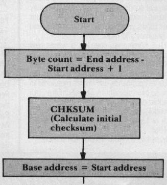
This invert operation should make the new checksum identical to the initial checksum. If the two checksums are not identical, the program terminates by printing the bit position and address where the error was detected. Otherwise, the program reinverts the current test bit, to restore its original state.
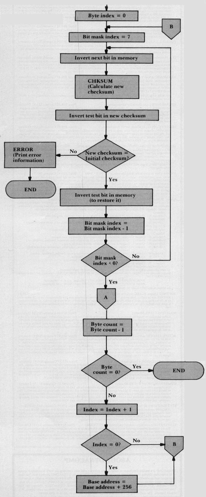
Figure 2: Checksum-Calculating Subroutine (CHKSUM)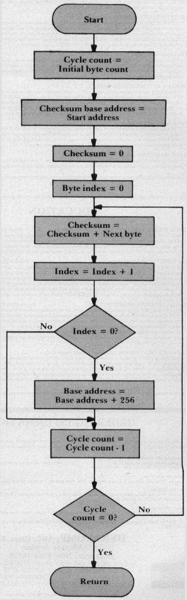
The remainder of the program involves a series of three counter/index adjustment operations, with each followed by a branch/no-branch decision. In the first of these operations, the bit mask index is decremented; if it is nonnegative, the program branches back to invert the next bit. Otherwise, the byte count is decremented; if all bytes have been tested, the program terminates, error free. Otherwise, the byte index is incremented. The byte index is eight bits long, and can hold values from 0 to 255 (decimal). If the incrementation caused the byte index to overflow to zero, the program increments the high order byte of the base address, then branches back to reinitialize the bit mask index. Otherwise, the branch takes place with no change to the base address.
Figure 2 shows the flowchart for the checksum subroutine, CHKSUM. This subroutine is called from two places in the program: (A) it is called at the beginning of the program, to calculate the initial checksum, and (B) it is called from within the main loop, to calculate a new checksum after a test bit has been inverted. This second source of call requires the subroutine to maintain its own, separate byte count and base address, so as not to disturb the current values of these parameters in the main program. In the flowchart, these "working" parameters are labeled cycle count and checksum base address, respectively.
To start, cycle count is set equal to initial byte count, checksum base address is set equal to test start address, and the checksum and byte index are initialized to zero. The rest of the subroutine is just one big loop. In this loop, the checksum is accumulated, byte by byte, with intervening index and cycle count adjustments. The loop is terminated when all bytes have been processed; that is, when cycle count has been decremented to zero.
The Test Program
Now that you understand the criteria of the program and its sequences, we can look at the program itself. Program I shows the source code for the nondestructive test program, which was flowcharted in Figure 1. Note that before executing the program, the starting address must be stored in locations 00 and 01 (00 holds low byte) and the ending address must be stored in locations 02 and 03 (02 holds low byte).
Besides these four locations, the program uses 13 other zero page locations, as working storage. These include six parameters that are used in the main program – initial byte count (IBYTES), byte count (BYTES), base address (BADDR), initial checksum (CSUM) and temporary storage for the X and Y registers (SAVEX and SAVEY), and two parameters that are used in the checksum subroutine, a working copy of the byte count (CYCLES) and a checksum base address (CBADDR). Of these parameters, only IBYTES and CSUM remain unchanged throughout the program; all six other parameters will change during execution.
Following these reserve equates come three equates that reference subroutines in the AIM 65 monitor: CRLOW initializes the display and printer to their START positions; NUMA prints the contents of the accumulator, as two ASCII digits; OUTPRI sends one character to the print buffer. Other 6502-based computers have equivalent subroutines.
The actual code that follows is straightforward, so you should have no problem following it if you studied the flowchart in Figure 1. Some readers may wonder why I chose to save X and Y in zero page (locations SAVEX and SAVEY), rather than on the stack, during the call to CHKSUM in the main loop. There are two reasons why this was done:
- The instructions used to save X and Y in zero page execute eight cycles faster than those to save X and Y on the stack (12 cycles versus 20 cycles). If you consider that for each byte tested, CHKSUM is called eight times – once for each bit position – saving X and Y in zero page saves 64N microseconds for an N-byte test run.
- We need to use the checksum contents of the accumulator upon return from CHKSUM, and a pull from the stack (PLA) always loads the stack information into the accumulator. If the 6502 had the instructions PHX, PHY, PLX and PLY, the stack would have been the likely place to hold X and Y, but unfortunately it has no such instructions.
Programmers may also be interested in the way the bit masks are accessed by the EOR BMASK, X instructions that follow the labels INVERT and NXTBIT. The bit mask table, BMASK (shown at the end of Program 2), is arranged by ascending bit position. That is, the mask for Bit 0 comes first, followed by the mask for Bit 1, and so on. However, this table is accessed in descending order; Bit 7 is tested first and Bit 0 is tested last. This allows us to initialize the bit mask index to 7 (LDX #7 at label IBMSK), then decrement this index until it goes negative. Otherwise, working with a descending table and an incrementing index, the program would have to include a CPX #8 instruction to make the done/not done branch decision. By using the ascending table and decrementing index approach we've eliminated that compare instruction. Since the CPX #8 instruction executes in just two cycles, the difference in approaches is not significant, but the backwards access is a handy gimmick for your programming bag of tricks.
Program 2 shows the code for the checksum calculating subroutine, CHKSUM, which was flowcharted in Figure 2. It follows the flowchart closely, and needs no additional explanation. Program 2 also includes the previously mentioned bit mask table, BMASK, and the text for the error message.
This program will produce one of two messages. If the test memory is error free, the message OKAY! will be printed, otherwise an error message of the form BIT n OF LOG. aaaa will be printed. In the error message, the bit position and address that are printed identify the bit that was being tested when the checksum mismatch occurred. It's possible, of course, that inverting that bit actually caused some other bit in the memory to be inverted, due to crosstalk, so the printout position may not be the actual culprit. One way of finding out is to run a second test, starting at the location following the printout location; that is, rerun the test starting at "aaaa+ 1."
Execution Times For The Test Program
As you can see from the listings, the program occupies slightly less than a page of memory; to be exact, it occupies 245 bytes. Of even greater significance, however, is the amount of time it takes to execute. That is, the amount of time it takes to test a selected portion of memory. In a test that I ran, the program took just over four minutes to check out a 1K portion of memory (1024 bytes).
At first I suspected that something was wrong with the program, but after a few calculations I became convinced that this was indeed a respectable time, in light of what the program was doing. First, consider that in a 1K byte test, the CHKSUM subroutine is called 8193 times; once to get the initial checksum, then once more for each of the 8192 bit positions in the 1024 byte test memory. The CHKSUM subroutine takes 28 + (29 × N) cycles to calculate the checksum for an N-byte memory, so it takes 29,724 cycles (microseconds) fora 1024 byte memory. Cranking out the math, we find that with 8193 calls, the program spends about 4.06 minutes in the CHKSUM subroutine!
|
Exclusive-ORs And Checksums An exclusive-OR is a logical operation in which two byte operands are combined to produce a result byte with these characteristics:
These rules can be summarized as follows:
All of the popular 8-bit microprocessors have an exclusive-OR instruction. In the 6502, it has the mnemonic EOR. The EOR instruction operates on the contents of the accumulator with an immediate value or a value in memory, and leaves the result in the accumulator. For example, if the accumulator contains the value $AB (where $ denotes hexadecimal) and location $40 contains the value $0F, the instruction EOR $40 will produce a value of $A4 in the accumulator. The binary arithmetic looks like this:
Note what has happened here. The value $0F in location $40 has caused the four low order bits (0 through 3) to be inverted, but has left the four high order bits (4 through 7) intact. This shows one of the primary uses for the EOR instruction: to invert some selected bits, but leave all other bits unchanged. In fact, the test program in this article uses the EOR instruction to invert a single bit in memory, by reading the appropriate memory byte into the accumulator, then exclusive-ORing it with a "mask" value that has just one bit set to logic 1. To invert Bit 7, the program applies a mask value of 100000002 ($80); to invert Bit 6, the program applies a mask value of 010000002 ($40); and soon. The program in this article also uses a series of EOR instructions to calculate a checksum value. As mentioned in the article, the checksum is the exclusive-OR of all bytes being tested. For example, if locations $0400, $0401 and $0402 are being tested, the program will perform this type of operation:
|
Since the program is spending virtually all of its time in the CHKSUM subroutine, the total execution time of the program is directly dependent on the efficiency of this subroutine. If any readers have suggestions on how to streamline CHKSUM, I'd be happy to hear from them.