THE SBC GAZETTE
Nuts and Volts
Gene Zumchak
In my last N&V column (Nov/Dec), I talked about parallel interfacing techniques, and intended to talk about serial techniques in my next column. Before that column reached print, however, Eric Rehnke, quite independently, wrote up the same subject for his January column. Until I read Eric's column, I actually thought I had covered the topic. Shame on me. Between our two columns, I think we have probably raised more questions than we have answered. Since Eric at least provided a pair of programs, his treatment was certainly more complete. So with a little egg on my face, I'm going to take another shot at handshaking.
Handshaking is a scheme by which data can be transferred between two asynchronous systems (1) without error and (2) at the fastest possible rate. While number one is always a requirement, two may not be. Still, it is usually desirable to perform a handshaking transaction in the shortest possible time.
True handshaking requires that one flag each be asserted by the sender and receiver. The nature, polarity, and names of these flags are not standard, and a large number of variations are possible. Typical names for the flag asserted by the sender are DATA READY, DATA AVAILABLE, and DATA VALID. The flag asserted by the receiver is sometimes called BUSY, DATA TAKEN, or ACKnowledge. When looking at an already defined handshake sequence, be sure to note whether flags are high-true (active-high) or low-true.
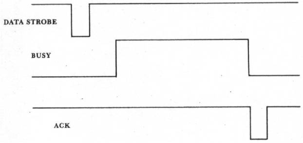
The handshaking signals most likely to be encountered by a computer user are those used with a parallel printer, often called "Centronics" handshaking. Eric stated in his article that he "decided to simplify it (the "Centronics" handshaking signals are shown in Figure 1. Note, that although there are three handshaking lines, this is NOT a three-wire handshake. The line asserted by the sender is a pulse called DATA STROBE (usually low-true). The receiver (printer) responds by raising a BUSY flag (usually high-true). Alternatively, the sender can choose not to use the BUSY flag, but instead use a third flag called ACK, which is a low-true pulse which occurs at the trailing edge of BUSY, indicating that the printer is no longer BUSY and can accept characters again. The two flags from the printer are provided as a convenience. They convey the same information and only one or the other need be used. Consequently, the so-called "Centronics" handshake is indeed a two-wire handshake. Traditionally, the level signal (BUSY) is used when handshaking is serviced using polling. The pulse signal (ACK) is used to set an interrupt flip-flop, when interrupt servicing is used. (If there are more than one receiving devices, a two-wire handshake will not suffice. A three-wire handshake, invented (and patented) by Hewlett Packard, is used on the IEEE-488 GPIB to accommodate multiple receivers. This bus will be discussed in a future column).
A very typical handshake sequence is shown in Figure 2. The flag asserted by the sender is a low-true DATA READY. The flag returned by the receiver is called BUSY and is high-true. The sequence is as follows:
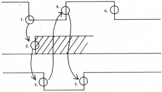
- Sender polls BUSY and waits for BUSY to become false (not busy).
- Sender places data on the data lines.
- Sender asserts DATA READY.
- Receiver acknowledges receipt of data by raising its BUSY flag.
- Sender removes (raises) DATA READY.
- Receiver lowers BUSY when ready for new data.
This sequence can be seen to be equivalent to that suggested by Eric, except that his DATA READY is a high-true signal. The choice of signal polarity given here is consistent with the operation of programmable port chips. I/O pins on such chips come up from reset as inputs and are high. Thus the DATA READY naturally comes up in the false state. For the receiver, the BUSY comes up naturally high, so that no sequence can be started until the receiver program is started and its BUSY line is cleared. It will not matter, therefore, whether the receive program or the send program is started first.
Just as the data direction registers come up zeroes from reset defining inputs, the data registers come up zeroes as well. Therefore, it is a good idea to write output data to port bits BEFORE configuring the bits as outputs. If the port bits are made outputs first, they will immediately fall to zero, since the reset line zeroes the data register. Even if the program immediately writes ones to the outputs, all output lines will experience a momentary glitch to ground (for the duration of an instruction) until the new data is written. It is important to understand that data can always be written to ports as outputs, even if they are programmed as inputs. Making a bit an input bit merely disconnects the flip-flop from the I/O pin. Even though you will not be able to read the data that you have written to an output bit, it is still in the flip-flop. A representation of a programmable port I/O bit (PAO) and the corresponding data direction register bit is shown in Figure 3, and is worth discussing.
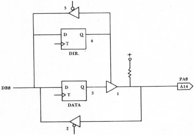
The flip-flop (item 3) has its "D" input connected to the data bus bit DBO. It can serve as an output bit if and only if it is connected to the port pin PAO via the three-state gate (item 1). With this gate enabled, anything written to the zero bit of a port A will appear on the I/O pin. If the gate is disabled, however, we are now free to use the I/O pin as an input. Note, however, that programming the bit as an input DOES NOT PREVENT US FROM WRITING TO THE DATA flip-flop. While we will not be able to read the data back, the data is still in the flip-flop, and it will appear on the I/O pin if this bit is subsequently made an output. When the port is read it is the condition of the I/O pin that is being read, regardless of whether the bit is programmed as an input or output. (This is not true of B ports, where the data read back when programmed is the latched data. That is, a bit can be programmed as an output and a one and the I/O pin shorted to ground and have it read back as a one). The three-state gate (item 1) is controlled by a second flip-flop (item 4) called a data direction flip-flop. This condition of this flip-flop may be read via its three-state gate (item 5). (Note that what we have called a three-state gate is in actuality implemented with MOS open-drain technology).
The purpose of this discussion was to convince the reader, that it is possible to successfully write output data to a port while it is still programmed as input. Not only is it possible, but it is recommended as good port software technique, to avoid unnecessary output "glitches".
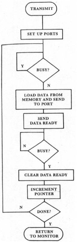
Getting back to handshaking, it is now necessary to look at handshaking software. We would like to consider both the transmit and receive programs. Figure 4 shows a flowchart for a transmit program. First the ports must be set up. Then before transmit�ting, we must be certain that the receiver is not BUSY, and wait until BUSY is false. Then data is loaded and sent to the port. Next the DATA READY flag is lowered. The program now waits for the handshake resppnse from the receiver, that is, for BUSY to become true. As soon as that has been verified, the DATA READY flag is cleared and the memory pointer is incremented and compared with the end pointer. If the end has not been reached, the process is repeated for another byte. Otherwise the program returns to the monitor.
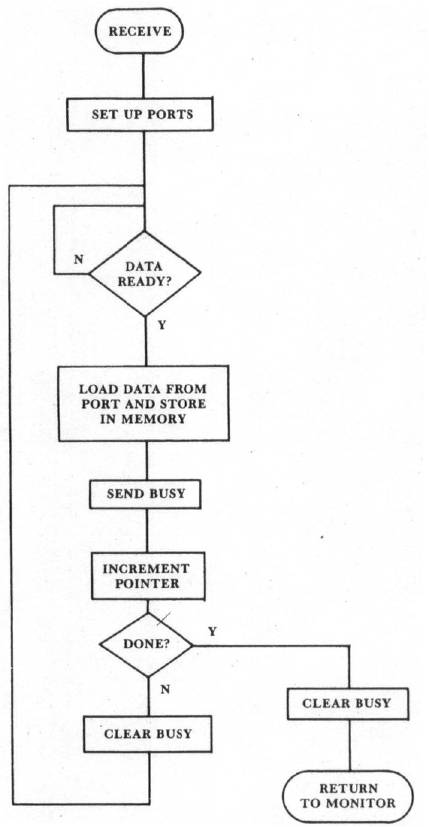
A flowchart for a receive program is shown in Figure 5. After initialization, a wait is made for a DATA READY indication, then the data is tucked away, the BUSY flag raised, and the pointer incremented. At this point, the pointer may be compared with an endpoint for a completion test. If done, the BUSY flag is lowered and a return made to the monitor. If not, the BUSY flag is lowered and another data byte is fetched.
Both transmit and receive programs can vary, depending upon whether speed or code conciseness is the most desirable feature. This discussion will be continued in the next column with an analysis of typical transmit and receive programs.