
Floppy
DRiVE Mods ANd REPAiRS
by PAUl AlhART, AC STAff ColUMNiST
W/P Stuff
Although no longer in production, the Atari 810 and 1050 drives are still probably the most common storage devices in use today by us 8-bitters. As a result, there have been several commercial and home-brew modifications for these drives. One that I had never seen, however, was the addition of a Write Protect Light. A W/P light indicates if a disk is write protected or not. My Rana drives have W/P lights. Although they are not a necessary item, I have really come to depend on mine to help avoid mishaps during operations that require heavy disk swapping. W/P lights can also be found on Indus and Trak drives.
This month's column deals with the installation of a W/P light and Write Protect Switch to your 1050 drive, as well as tips for common repairs to various Ataricompatible drives. The W/P switch lets you select any one of three different Write Protect modes at any time. (There's no need to turn power off or even wait for the "BUSY" light to go out when switching modes.) Be aware though, if the drive is switched to the PROTECT mode during a write operation, an error will be generated and the write operation will be aborted. The three modes are:
Mode 1: "UNPROTECT" This mode allows you to write to un-notched disks or disks that have Write Protect Tabs on them. It will also allow you to write to the "flip" side of disks without having to cut a newnotch.
Mode 2: "PROTECT" This mode will force the drive into Write Protect mode even for notched disks. All disk writes are disabled.
Mode 3: "STANDARD" This mode sets the drive for normal (unmodified) operation. Only notched disks can be written to.
Although either modification could be done separately, you can add them both for only about $5.00. Together they'll give you 100% control over the drive's write protect function along with a visible indication of the write protect status.
What's Required?
As with all hardware projects, you'll have to begin this one with a quick trek to your local electronic parts supplier. Since for many readers that means Radio Shack, I've included RS catalog numbers for your convenience. Purchase the following items:
1.) A SPDT 3-position "ON-OFF-ON" switch (#275-325);
2.) A 330-ohm 1/4 watt resistor;
3.) A light emitting diode or "LED" (#276-026);
4.) Approximately 24 inches (60cm) of insulated hookup wire;
5.) Rosin-flux solder.
With parts in hand we're now ready for business. I'll assume you already have a soldering iron and the usual assortment of small hand tools.
Getting Started
Before you even remove your drive from your system, stop and look things over. Decide where the best location for the switch and LED will be. Since you'll have to drill mounting holes in your drive's case, you have to get this right the first time. On the 1050 drive, I found the best location to be on the downward sloped bevel on the right side of the front panel. Wherever you decide, make sure there is clearance inside the drive case for your components before drilling any holes.
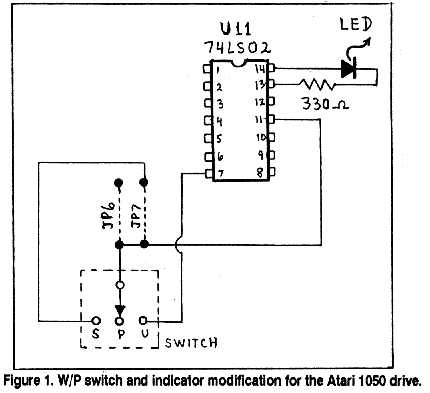
Refer to the schematic diagram in Figure 1 below for installing the W/P switch and LED indicator in your 1050.
Going Inside
Remove the drive from your system and flip it over. Remove the six screws that hold the case together. Flip the drive back right side up and lift the top half of the case off. The front panel usually comes off with the top case half and can just be unsnapped from it if desired. Before going any further, get a paper and pencil and make note of the orientation of the seven connectors linking the drive mechanism to the printed circuit board (PC board). There are five connectors on the left rear side of the board, one on the right rear side and one on the right front side.
These connectors will have to be removed, and if you reconnect them backwards or in the wrong order you could cause permanent damage to your disk drive. Using a small pair of pliers, grasp the plastic portion of the connector (NOT THE WIRES!) and pull it straight up off the PC board. CAUTION: Most problems encountered when performing mods to 1050 disk drives occur at this point. The wires can easily be ripped from their connectors if they're yanked too hard. Easy does it! After all the connectors have been removed from the PC board, lift the drive mechanism straight up and out. Grasp the drive mechanism by its sides. Never lift or hold it anywhere near the head assembly. Set the drive mechanism aside in a safe clean place.
ESD Caution
Although you won't be removing any ICs, you'll be working directly on the PC board. Take normal precautions against ESD (electrostatic discharge). If you don't know what I'm talking about here, STOP! There have been many good articles written on the subject of ESD. Read one of them before you proceed. If necessary, I'll be glad to cover ESD further in a future article. Many of the components in your system are static-sensitive and could be damaged if you're careless in this area.
Spread the two plastic clips in the lower case half that hold the front of the PC board in the case. Remove the PC board from the case. Remove the RF shield from the PC board by straightening out the four metal tabs on the bottom side of the PC board. Locate U11 (a 74LS02 NOR gate) and JP7: they're on the PC board in the area under the RF shield you just removed. You should be able to easily spot the row of jumpers including JP7; U11 is the closest component to the jumper.
Installing The W/P Switch
If you're installing the W/P switch, remove JP7. Locate the solder pad of JP7 that's common with the pad of JP6. This is the pad toward the rear of the PC board. From this point, connect a wire to the center contact of your W/P switch. Connect a wire from the other JP7 pad to one of the W/P switch's end contacts. Connect a wire from the contact on the other end of the switch to U11 pin 7 (GROUND).
All that's left to do now is mount the switch. I found that positioning the switch so that UNprotect was on the left and Standard was on the right made its operation easy to remember. Just think of the shipping outfit, UPS, when making a selection. I guess "Uninterruptable Power Source" would do just as well!
Installing The W/P Light
Connect U11 pin 13 to a 330-ohm 1/4 watt resistor. Connect the other end of the resistor to the cathode of the LED. The cathode is the longer of the LED's two leads. Connect the other lead of the LED (the anode) to U11 pin 14 (+5V). Mount the LED and you are done. You might need a small dab of RTV silicone or glue to hold the LED in place.
Reinstall the RF shield. Note that the notched portion of the upper half is over U14 and R43. Insure that the added wires aren't pinched by the RF shield. Install the PC board in the lower half of the case. Set the drive mechanism back in place on its mounting pins. This can sometimes be the most challenging part of the whole project! Now plug the seven connectors back onto the PC board. Again, be careful here. Be sure they're positioned correctly. Replace the top case half and front panel, flip the drive over, and replace the six screws.
Testing
The drive is now ready to test. Before placing it back in service, connect the power supply and turn power on. The busy light should light for a few seconds during which time the head stepper motor and drive motor can be heard. If the drive motor doesn't run or won't stop, or the busy light doesn't light or won't go out, turn power off. Recheck all the connectors to ensure they're positioned correctly and that none of their wires have been pulled loose. After insuring everything is OK to this point, put the drive back on line. With the new W/P switch in the center position the W/P light should be ON, indicating PROTECTED mode. Flip the W/P switch to one of its end positions and insert a write protected disk. If the W/P light comes on, this is the STANDARD mode. If the light doesn't come on, it's in UNPROTECT mode.
Both of these modifications are the type that, after a few weeks, you'll wonder how you ever got along without them. If you feel uneasy about opening your drive and poking around with a soldering iron, find someone qualified to help you. As a service to Atari Classics readers I offer installation of both 1050 W/P upgrades for $25. This includes parts, installation, cleaning and alignment of the drive mechanism, and return shipping. To take advantage of this offer, or if you'd like to see similar upgrades published for other disk drives, let me know!
Drive Weirdness
Having repaired hundreds of disk drives for the 8-bit Atari, I thought I'd seen just about every type of failure and kludge there was. There were the usual failures due to dirt, misalignment, and faulty power supplies. And then there were the oddballs, like the 1050 that had a can of cherry cola dumped into it. Some of the user fixes I've seen were pretty ingenious too, like the Rana that had a guitar string used to replace the head positioning band. (A better solution would have been to use the band assembly from an Atari 810 MPI drive mechanism. Atari part #FA100034, from Best Electronics. This is a direct replacement for the band assembly used in the Rana.)
Belting Your 1050
Recently a new problem has been showing up in 1050 drives with the World Storage drive mechanism. The drive belt keeps falling off for no apparent reason. When this happens the disk stops turning. Even though the busy light comes on and you can hear the motor running, the drive won't read or write to any disk. If this is happening to your 1050, fear not. The explanation is fairly simple, and the fix is even easier.
In what I consider a design flaw, World Storage failed to include a belt retainer on their drive like Tandon did. This wasn't a problem when the drives were new. Now, however, a few years later, when the spindle bearings are starting to wear, it's becoming a problem for many 1050 owners. The slightest tilt of the spindle due to sloppy bearings causes the belt to track right off the edge of the pulley. Atari didn't switch from Tandon to World Storage drive mechanisms till near the end of 1050 production. This explains why the problem is just now starting to show up.
As I said, the fix is easy, and it won't cost you anything but a few minutes to make it. Just follow the procedure outlined below to add a belt retainer to your 1050.
Step 1: Disconnect the drive from your system and flip it over.
Step 2: Remove the six screws holding the case halves together. (Four are in recessed holes in the case.)
Step 3: Flip the drive back right side up and lift off the top half of the case.
Step 4: Lift the drive mechanism from the front without putting any undue stress on the wires running from the drive mechanism to the controller board.
Step 5: Locate the spindle pulley. If it's fully exposed to view you have a World Storage drive mechanism and should proceed with the fix even if you haven't had a belt problem yet.
Step 6: Cut a disk from the top of a plastic butter or Kool-Whip tub. Use a compass or drinking glass as a guide to make the disk about 1/4" larger in diameter than the spindle pulley.
Step 7: Glue this plastic disk to the bottom of the spindle pulley. Hot-melt glue works really well for this.
Step 8: Reinstall the drive mechanism by setting it down on its guide pins.
Step 9: Replace the top cover and the six screws removed in step 2.
Step 10: Reconnect the drive to your system. The plastic disk acts as a belt retainer and should allow you to enjoy many more productive years from your 1050.
Wake Up Your 810
Does your 810 occasionally turn itself off or refuse to power up? This is a fairly common problem that can usually be traced to a burnt or corroded pin on the Side Board connector. This is the 23-pin connector that may be labeled J101 or J106, depending on which version of the 810 you have. Follow the steps outlined below to "wake up" your sleepy 810.
Step 1: Disconnect the drive from your system.
Step 2: Remove the four screws holding the top case half. These screws were originally hidden under circular plastic covers held in place by rubber cement. If your drive still has the screw covers, pry them off with a knife blade to gain access to the screws.
Step 3: Lift off the top case half.
Step 4: Remove the five screws holding the drive mechanism in the lower case half.
Step 5: Remove drive mechanism from the lower case half by lifting it straight up.
Step 6: Remove the three screws that hold the Side Board in place.
Step 7: Make note of the orientation of all connectors attached to the Side Board and carefully remove each one. NOTE: pull only on the connectors. DO NOT pull on the wires.
Step 8: Remove the Side Board by gently rocking it end to end, while pulling upward.
Step 9: Examine the 23-pin connector for signs of corrosion or discoloration. Extreme cases may show signs of melting or distortion of the plastic. Also examine the pins this connector mates with. Pay close attention to pins 1, 2, 10, 12, 13, 14, and 15. These are the pins that carry the most current.
Step 10: Clean any corrosion with contact cleaner or alcohol. An old toothbrush will help here. A pencil eraser will work well for the mating pins. Extreme cases may require replacement of the connector, which I won't get into here.
Step 11: Reinstall the Side Board, making sure the pins are aligned properly. It is possible to be off a pin on either end, so double check before reinstalling the screws.
Step 12: Replace all the connectors in their original positions as noted in Step 7.
Step 13: Replace the drive mechanism back into the lower case half and replace the five screws removed in Step 4.
Step 14: Replace the top case half, its fours screws and screw covers.
Step 15: Reconnect the drive to your system and test.
Help Your Trak Quit Smoking
On some Trak drives the power supply connector can make intermittent contact with the metal back plate of the case. This causes the internal bridge rectifier to go up in smoke. To eliminate this problem, remove the case and make the access hole in the back plate bigger with a drill or file. Be careful not to let metal debris get into the drive mechanism or the electronics. I don't have a Trak drive available to look at as I write this, so you'll have to figure out how to remove the case on your own.
Indus Owners Beware!
In the beginning, and through the 1200XL, virtually every Atari product used a 9-volt AC power pack. The small 1/4" diameter connector on this power pack is easily distinguished from the larger 7-pin DIN connector used on the +5 volt DC power packs of the XL/XE line of computers. Crossing the 800's power pack with the one from your 810 causes no problems because both devices use the same 9 volt AC power. These power packs are also interchangeable with those used by Trak and Rana drives as well. NOTE: some of the earlier Atari power packs had smaller wattage ratings and may not be appropriate for heavily expanded or modified equipment.
The Indus GT power pack looks the same as the Atari power pack. It even has that same 1/4" connector that will plug right into your Atari, Trak, or Rana. This power pack, however, puts out 9 volts DC. Accidentally plugging an Atari AC power pack into your Indus will cause unwelcome clouds of smoke to fill the room. I recommend conspicuously marking your Indus drive and its power connector with a warning to this effect. This will help keep your Indus healthy, especially if the kids get to messing around with your system.
Rana Guide Available
I've written a useful booklet called The Rana Repair Guide for Rana owners. For more tips on repairing and modifying your Rana, as well as complete schematics and alignment instructions, order your copy today. It's just $10.00 +$2.00 P&H.
And let me know if you'd like to read more about the Atari disk drives!
