
TTL
VidEo FOR ThE CIASSic ATARi
by
Bob WoollEy, AC STAff REViEWER
Which Monitor?
One of the issues confronting users of classic Atari computers today is the selection of a suitable monitor for your system. Unfortunately, no one display will provide optimum performance under all conditions. A color monitor, for example, builds a pixel out of triads of red, blue and green dots. This produces a pleasing display when viewed at a distance, but quickly becomes grainy and indistinct as you get within a few feet of the screen. A monochrome monitor doesn't have the color screen's resolution problem, but graphics lose much of their personality when displayed as shades of a single color. The newer VGA monitors have much smaller color triads which give them both unlimited color and high resolution, but they run at much too high a frequency to be used on our classic 8-bits. So, we have to compromise: text clarity or color graphics?
If most of your time (like mine) is spent in text modes, a monochrome monitor is really your best alternative. A good television with direct video inputs will fill in for those occasional games and demos, while the bulk of your computing (programming, word processing, telecommunicating, etc.) can be done on a nice sharp monochrome screen. Sadly, the supply of high quality analog displays is very limited since most computers (read: IBM) are now built with TTL (digital) interfaces. (See "Super Video 2.1XL" elsewhere in this issue for a more general discussion of video interfaces.)
Unmodified, the Atari requires an analog NTSC or PAL composite monochrome monitor which are practically impossible to find any more. All you see for sale are these days are TTL units (and even those aren't quite as popular as they were a few years ago). What we need is a way to interface our Atari to a TTL monochrome monitor that we can use for text displays while keeping our composite output for color graphics. That's the subject of this upgrade.
TTL Caveats
By adding my circuit to your 8-bit, you'll be able to run two separate monitors on your Atari: the normal composite sources and a 9-pin TTL device. I've used the TTL interface to drive both color IBM CGA (Color Graphics Adapter) monitors as well as monochrome IBM MDA (Monochrome Display Adapter) displays, although the wiring needs to be modified for each type.
Why use a CGA display? Well, the MDA interface only has the capability to display four levels of gray, where our Atari will normally output eight. This isn't much of a problem in most text modes, but does leave a few holes in graphics. PacMan, for example, loses two of its ghosts in the background when run on an MDA display. On the CGA monitor, we can display all eight intensity levels, each as a different color rather than shade. Text still suffers from the pixel size, but it does make a very clear and colorful alternative to MDA. Keep that in mind when you plan your configuration. Otherwise, the text on a TTL monitor is razor sharp and much easier on the eyes than any color monitor.
Another concern is the frequency difference between the 8-bit and an IBM. Horizontal sync frequency on a standard MDA monitor is 18kHz, while the Atari runs at 15.75kHz. To check for problems in this area, I tested a number of MDA displays on the upgrade. Most ran just fine, with some needing slight horizontal or vertical frequency adjustments. Making these adjustments can be significant if you're using a monitor like the IBM 5151. This model has no external controls! I had to remove the cover (no simple task) and adjust the pots inside the cover. Another negative for the IBM 5151 is the slow P39 phosphors used on the screen. This long persistence surface causes a smeared image as an object is moved or scrolled. I can't recommend the IBM, although it does work with the interface. I suggest a good amber screen with a high contrast filter like the Amdek 310A or Samsung SM-12SFA7. These monitors provide an excellent text display and are widely available.
Doing The Mod
The construction method I used on this project allows you to build the board and simply plug it into your computer: no wires need to be soldered to your motherboard. I prefer this technique since it makes it easy to remove the modification in case of a problem, and it allows a friend to build you a board without your system being out of service.
I used half of a small Radio Shack perfboard (#276-148) and 30 gauge wirewrap wire to mount the components. Sockets are optional but recommended. You'll have to remove the 4050 video buffer from its socket on your motherboard. If it's not socketed, cut it off the board and add a socket.
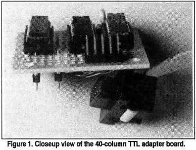
I used .018 diameter standoff header pin connectors to plug into the vacant 4050 socket. [These type headers are hard to find but are used in the Wizztronics 256K RAM upgrade and are available from Best Electronics. BP] This provides us with all the necessary signals and power. See Fig. 1.
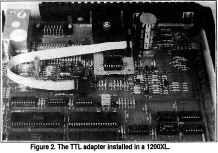
The output cable is a short length of nine conductor ribbon cable with an IDC female DB-9 connector on one end and a ten pin dual row header-pin connector on the end that connects to the board. I mounted the DB-9 connector on the case of my 1200XL, but you can just run it out through the case seam if you like and let it hang free. The installed TTL board and cable are shown in Fig. 2.
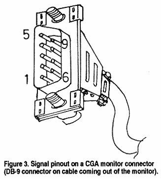
Refer to Fig. 3 and the table below for a pinout description of a typical TTL monitor:
|
Pin # |
Signal |
| 1 |
GND |
| 2 |
GND |
| 3 |
Red
(1) |
| 4 |
Green (1) |
| 5 |
Blue
(1) |
| 6 |
Intensity |
| 7 |
Video |
| 8 |
H-Sync |
| 9 |
V-Sync |
Take note of the two designations for pin 8 of the DB-9. One is for a CGA monitor, and the other is for an MDA monitor. These monitors use different sync polarities and may or may not work with the wrong polarity. [A few brands of monitors have a switch in the back for positive or negative sync. The enterprising hacker might elect to install a switch here if your monitor lacks one. -BP] Choose CGA or MDA when you wire up the board (or install a switch). It won't hurt anything if you use the wrong polarity; your monitor just won't have a stable display.
I laid out the schematic diagram (Fig. 4) with all the inputs on the left (from the 4050 signals on your Atari motherboard) and all the outputs on the right (through the ribbon cable to the DB9 connector). Not all models of classic Ataris use the same sections of the 4050 IC for the corresponding signals. The 4050 inputs are labelled LUMO, LUM1, LUM2, LUM3, and CSYNC. Corresponding pins on the 4050 in your particular model are as follows:
| MODEL | LUMO | LUM1 | LUM2 | LUM3 | CSYNC |
| 130XE |
7 |
11 |
5 |
3 |
14 |
| 800XL |
7 |
11 |
5 |
3 |
14 |
| 600XL |
9 |
7 |
11 |
5 |
14 |
| 1200XL |
3 |
9 |
7 |
5 |
11 |
| 800 |
5 |
9 |
14 |
11 |
7 |
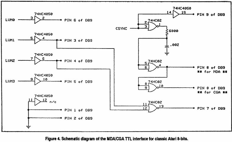
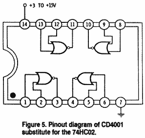
A final word about parts. You can substitute a standard CD4050 noninverting hex buffer for the 74HC4050 I used; the pin numbering is the same, and the CD4050 is readily available at Radio Shack. You can also substitute a standard CD4001 quad two-input NAND gate (also available at Radio Shack) but be careful! The 4001 has a different pinout than the 74HC02 shown in the diagram. Refer to Fig. 5 for the pin description of the CD4001. As long as you stay with CMOS gates this project should work all right. DO NOT USE STANDARD TTL OR LS-TTL TYPE LOGIC CHIPS!! They may not work at all, or performance may suffer in unpredictable ways.
Also, the IDC crimp-on style DB-9 connector isn't available at Radio Shack, though many mailorder parts houses such as Jameco or Digi-Key sell them. If you elect to mount the DB-9 connector on the rear of your machine, a panel-mount type is available at Radio Shack (#276-1538).
Only Half The job
You can wirewrap all the connections on the underside of the plug-in board as seen in Fig. 1. After everything is installed and hooked up, you might see some tearing or screen rolling on your TTL monitor when you boot up the computer. Adjust the monitor controls for a clear, stable display. I think you'll be impressed with how crisp it looks on an MDA monitor. Your usual composite video signals are still available at the rear output jack on your 8-bit if you care to compare the analog and TTL displays. It might be interesting to do an AB test of Ben Poehland's Super Video 2.1XL or Charles Cole's XE analog upgrades to my TTL upgrade!
High-quality 80-column monochrome text has been available for the classic Atari for about six years now, and many of you who purchased them were no doubt impressed by the sharp display these units produce. But, you still need a hard-to-find analog composite monitor to enjoy the 80-column text. If you perform the 40-column TTL upgrade I've just described, and you have an XEP80 in your system, you end up needing two monitors: TTL for the 40-column output, and composite for your XEP80. So, at this point the job is only half done. Wouldn't it be nice if the XEP80 could also be modified for TTL video? Read on!
XEP80 Vs. Composite Video
The XEP80 is a nice addition to your classic Atari. The characters are well formed and crisp with none of the video problems you often get with an unmodified 8-bit. Unfortunately, once you decide to upgrade your system to an 80 column display using an XEP80, you have a problem. The XEP80 is designed to be used on a composite monochrome display, but most composite monitors these days are used in video applications (i.e., closed-circuit TV, security monitors in shopping malls, etc.), not computer data. This is a problem since a video frame is designed to overscan the edge of the screen while data frames aren't. This could run some of your data off the edge of the screen where you can't see it. (This is why our E: editor starts its text in column 2 instead of 0).
Coupled with the fact that video monitors have poor linearity and bandwidth, you'll probably be disappointed in the performance of your XEP80 on a monitor not designed as a computer display. It'll work, but not well. The solution is to use a high quality TTL monitor with your XEP80. They are easier to find at a reasonable price, have very high (18MHz) bandwidth, and come in easy-to-read amber, green, or paperwhite shades. Fortunately, the modification required to make your XEP80 work on a monochrome TTL MDA monitor is both cheap and easy.
TTL displays require separate horizontal and vertical sync lines and a digital data line to create the video image. These signals are all available in the XEP80 without adding any circuitry: all we need to do is wire in a cable! I used a 12-inch, nine conductor ribbon cable and a female IDC DB-9 connector. This cable runs from the bottom of the XEP80 board, under the shields and out through the back of the case where it hangs free. The modification doesn't affect the operation of your regular composite output and only takes about an hour to perform (once you've gathered all the parts, that is!).
TTL For The XEP80
Let's do the mod! Start by removing the four screws from the bottom case. Remove the lower case half and carefully pry the joystick cable retainer from the upper cover. Now you can remove the circuit board entirely. Remove the shields by straightening the six retaining tabs (make note of the shield orientation first).
Cut a length of 9-conductor ribbon cable 12" long. At one end, separate all the wires for a distance of about 2". One side of the cable will be marked with a colored (usually red) stripe. If the cable doesn't have a stripe on one side, make one with a marking pen. We'll use the mark to keep the cable properly oriented. Number the wires 1 through 9, with the marked wire being number 1. Now cut off the 2" free length of the following wires: 2, 5, 7, and 9. Strip 1/8" of insulation from the remaining five wires and "tin" the bare wire with solder. Set the cable aside temporarily.
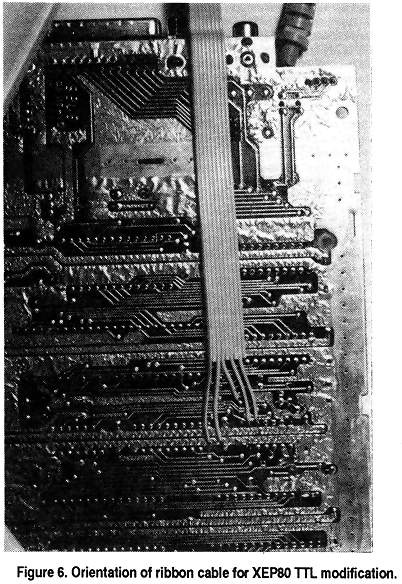
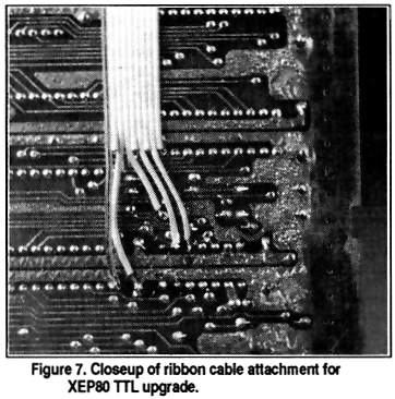
Now examine the circuit board and locate the IC marked U6 near the edge of the board. Also locate the 220 ohm resistor just above U6 labeled R3 (red-red brown-gold). Orient the board and cable as shown in Figures 6 and 7, with the colored stripe on the left. Solder the flat cable to the positions on the foil side shown in Figure 7, and refer to the chart below to insure the wires are all going to the right places:
| DS-9 Pin # | Connection |
| 1 |
U6,pin 7 |
| 2 |
U6,pin 7 |
| 7 |
left end of R3 (note) |
| 8 |
U6,pin 9 |
| 9 |
U6,pin 10 |
When you crimp on the IDC connector, orient the cable so the colored stripe goes to pin 1, and the signals should automatically be routed correctly to the right pins. As noted in the 40-column TTL upgrade above, getting the IDC crimp-on type DB-9 connector might be a problem. You can use the panel-mount unit from Radio Shack mentioned earlier, but it's more work as you'll have to solder the signal wires to each pin individually. If you do it this way, be careful: it's very easy to get the pin order reversed! Also, you'll have to insulate the connector when you're done, preferably with heatshrink tubing from Radio Shack.
Now reassemble the shields and case in reverse order, and you're ready to go! As I mentioned earlier, you might have to make some adjustments to your monitor's horizontal or vertical controls, but all the monitors I tried would work after adjustment. If you made the TTL video modification to your computer as well, you can use a six pole, two position switch to select either 80 or 40 column mode, all on one monitor! Good luck!
[Alchemist's Comment: I tested one of Bob's modified XEP80's extensively and was very favorably impressed. The monitors I used were: Arcus DM-14T 14" paperwhite, Princeton Graphics MAX-12 12" amber, Amdek 310A and 410A 12" amber, and an IBM 5151 12" green. Ordinarily I use a modified DEC Rainbow VR-201A 11" paperwhite, Heath/Zenith HVM-122A 12" Amber, or Apple A2M2010 12" green composite monochrome monitors with my XEP80. My eyesight is rather poor, so all my composite monitors are tweaked up for best possible linearity and focus: screen detail and resolution have always been more important to me than color.
On all the TTL monitors 1 had to do at least some H-syne, V-sync, V-size and focus tweaking to achieve a satisfactory display. The actual adjustments were straightforward, but as Bob mentioned, getting to the controls was in most instances a pain in the neck. At first I wondered why the manufacturers take such pains to hide these controls, but then I reminded myself that these monitors are made for the IBM market. The average IBM user isn't expected to know how to adjust his monitor and will be expected to pay some grinning service technician a fat fee to do what those of us with common sense can do for ourselves. On the other hand, anode voltages on mono monitors typically run 14,000 volts and color even higher: 25,000 volts; you can fry yourself to charcoal if you don't know what you're doing.
So, how does the Bob's TTL upgrade stack up to my well-tweaked composite monitors? It was a close race, as the analog and digital displays were both excellent. But Bob's TTL interface has the edge over the analog displays. I'll even go so far as to state that a TTL-modified XEP80 is absolutely the cleanest display you'll ever see from any classic Atari.
Among the various MDA monitors there was marked variation in performance. The Arcus was my favorite. The large screen size, VGA-looking paperwhite phosphor, and etched-surface antiglare flat screen made it a pure pleasure to use. There's even a neat inverse-video switch on the back. (On the down side, tweaking it for the XEP80 was a nasty chore.) I paid $112 + slipping for this monitor, which is a tad expensive for an MDA (most go for well under $100), but it was worth it. I got it from Altex Electronics (11342 IH35 North, San Antonio Texas 78233, 800-531-5369 orders or 210-655-8882 info). Incredibly, all the other monitors I tested were junkers I fished from the trash (in today's environment the attitude seems to be, "If it isn't VGA, throw it out!").
Among the 12" monitors the Princeton Graphics was the best performer. Due to the employment of a dynamic focusing circuit this monitor was razor-sharp even around the corners of the screen where static-focused units start getting fuzzy. The Princeton also employed the same type of etchedsurface antiglare as the Arcus. It was rather big and klutzy, though, and its cosmetics resembled the IBM a little too closely for my taste.
The Amdek monitors are cheap, abundant,... and very popular. I don't know why. Sure, they're sharp and clear enough. But the antiglare treatment on the CRT surface, which consists of thousands of tiny lense-like carvings on the 310A and a kind of embedded thin-woven cloth on the 410A, creates a halo effect that squanders the advantage of the high resolution performance inherent in MDA displays. Worse, the textured surfaces on these units are easily scratched or abraded, which ruins the screen. Still, I see these things everywhere and most people seem not to mind. The analog version of the 310 employed the same weird type of antiglare treatment and was a always a favorite among Atari 8-bitters. Go figure.
The IBM was clearly the worst of the lot; Bob's negative commentary about it was altogether too kind. That awful long duration phosphor revealed all sorts of annoying events that never appear on the fast phosphor CRT's. Like, a line that appears down the center of the screen while the disk drive runs, and bright flashes of light that occur while Atari writer-80 is loading. The phosphor takes along time (14 years) to settle down after a screen rewrite. If you're into video masochism, hook up one of these to your system and play a videogame on it. But it does work, if you can stand it! - BP]
