

SUPER VidEO 2.1XL
An Old Project
I began investigating the 800XL's poor video performance in 1986 and never really stopped. How do you condense eight years of continuous research on one topic into one short article? You don't. No way around it, this is going to be one long article! However, before we can roll up our sleeves and start shoveling up the video manure Atari dumped on us, I must first render homage to various publishers who participated along the way.
Super Video 1.0 was published by Ed Dell in the February 1987 issue of the now-defunct ComputerSmyth magazine. It gave modest improvements in video performance but really only represented a single-pass attempt to solve a problem that went deeper than I realized.
My continued hacking at the problem led to the publication by Joe Waters of Super Video 2.0 in the September 1991 issue of Current Notes magazine. That article represented a real breakthrough in my understanding of 800XL video problems and served as the springboard for polishing up the mod and applying the concept to similar upgrades for the 600XL and the 1200XL. I'm grateful to Ed Dell and Joe Waters for releasing my previously published articles. Had they not done so, I probably wouldn't have continued the tinkering which resulted in this final solution to all XL-series video defects.
Hackers Vs. XL Video
Like all good researchers, we Alchemists take a keen interest in the efforts of others who work along similar lines, and I must acknowledge their efforts. In the February 1986 isue of Antic, John Borland described how to restore the missing XL chroma signal to the output jack via a 220-ohm resistor. The resistance value was wrong, and this mod did nothing to improve basic video performance. But he was on the right track.
Again in November 1986, Antic published an article by Jon Krahmer describing how to bring out the missing chroma via a capacitor. While Krahmer deserves credit for pursuing the subject in the face of shamefully abusive treatment at the hands of Atari Corporation, his approach again did nothing to solve basic video defects and was the poorest method for restoring missing chroma to the output jack.
In the July 1989 PSAN Magazine, Rich Gratzer presented his fix for 1200XL video problems. It was strictly the work of an amateur: basic video defects were again ignored, and color shadows were somewhat reduced at the expense of color saturation performance. Most of the parts employed serve no real purpose. He concocted his hack on the basis of touching his fingers to the video components (!) and had a little difficulty recalling details to rationalize his approach.
Finally, I must give special mention to AC's Bob Woolley for his efforts to remedy 1200XL video defects. Not because he was successful, but because he tried so hard. Bob did manage to clean up some of the mono problems, but the color demons held out firmly against him. In the August 1987, September 1989, July 1990, and November 1990 issues of the SLCC Journal, Bob went head-to-head with the 1200XL video beast. A few times he came close to slaying the dragon, but he ran out of gas just short of final victory. It must have been one of the few times the Invincible Woolley tasted defeat (or at least, something less than total success). One of his articles got posted to the 8-Bit Forum on CompuServe, where it continues to befuddle Classic Atarians to this day. But the sheer amount of guts and sweat Bob poured into the effort was impressive even by Alchemist standards.
Genesis of Super Video 2.1
Following the 1991 CN article I felt sure I had finally solved all the 800XL video defects. In the elapsed two years, however, with hundreds of hours spent in front of my CRT, I began to notice more subtle things. Color performance still wasn't the best, and worst of all the brightness of my video display varied according to the electrical load on the power bus of my 800XL. I've modified my XEP80 so it draws power from the joystick port: it sucks half an ampere. The addition of stacked cartridges, a P:R:Connection, multiple operating systems and a 1088K RAM upgrade triples the power drain compared to the 700mA or so a stock 800XL draws (I run my system off a monster IBM-type switching power supply). With the addition of each new electrical load my CRT display grew dimmer. I was dismayed to realize that after all that work there were still a few gremlins I hadn't exterminated.
The culprit proved to be not the video circuit itself, but components involved in supplying power to the entire video circuit. The video circuit is isolated from the rest of the power supply by an 820uH inductor, L5. The function of this part is to pass clean DC voltage to the video circuit while suppressing any video RF interference that could make its way via the power bus into other parts of the computer where supply-line noise might disrupt the digital circuits. A prudent design-on paper, anyway.
In a perfect world, an inductor-which is nothing more than a little coil of wire-passes DC current perfectly but suppresses AC according to the inductance value (expressed in units called Henries). Well-made (but expensive) inductors come very close to achieving this theoretical level of performance. But a cheap one, wound with very thin wire, will exhibit the properties of a resistor as well as an inductor. In a DC circuit, resistors waste electrical energy by dissipating it as heat: the voltage coming out is usually lower than the voltage you feed in. This is a desirable characteristic when properly applied, but a disaster in the wrong environment. A resistance in series with the power supply is in this instance very definitely the wrong application.
So, did Atari use the nice expensive inductors that would only squelch the AC noise but not eat up any of those precious DC volts? Hah! Guess again! Of course you know they used the cheap ones! This is, after all, Atari: a company where the shaving of pennies was (and still is) the ultimate expression of Corporate Culture. A clue to the crummy inductor was provided by the low voltage on the collector of output transistor Q5: about 4.3V in most stock 800XL systems. Yet, the voltage on my motherboard's main supply bus measured 5.1V. Atari's cheapo inductor squandered 16% of the power available to the video circuit! I pulled these inductors from several XL boards and measured their DC resistance: typically 10 ohms. Terrible! (It shouldn't be more than an ohm or two.)
In Super Video 2.1 (which I'll call S-V from now on) we'll replace this stupid inductor with a low-value resistor, beef up the associated filter capacitor to maintain a noise-free supply line, and make a couple minor changes in the video circuit to enhance color performance and signal strength a bit. S-V 2.1 will be "grafted" onto S-V 2.0, which I'll describe first. Before describing S-V 2.0 I'll give you some background on various video interfaces and provide a general description of the major video flaws in the XL-series machines. Then I'll follow up with instructions for installing S-V 2.1 in the 600XL and 1200XL.
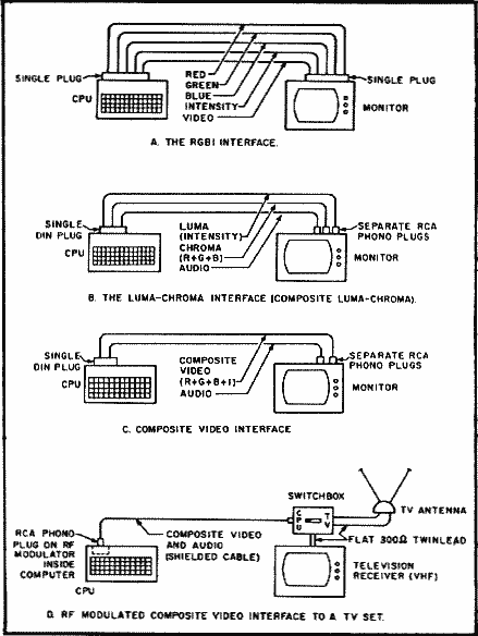
Figure 1. Typical Video Interfaces for Home Computers
(A) Digital RGBI Interface (CGA), all signals at TTL level, used in early IBM
PC's. Video is actually three separate lines carrying baseband video, H-
sync, and V-sync. For a monochrome display (MDA) only the Video,
Sync, and Intensity signals are used. Most IBM monitors lack Audio.
(B) Luma-chroma Interface for color monitors. A monochrome display Is
obtained if Chroma is disconnected. Luma alone can be used for best
picture on a CV mono monitor. Not all monitors have Audio.
(C) Composite video (CV) Interface. Used on color or mono monitors,
poorer performance than Luma or Luma-Chrome Interface.
(D) TV Interface, RF-modulated CV connected through TV antenna and
channel selector. Poorest performance, will ruin your eyes.
Video Interfaces
Figure 1 outlines various video interfaces used in home computers. Figure 1A is a simplified representation of the digital or TTL interface. This was used mainly in early IBM PC's, where it was implemented as CGA (Color Graphics Adaptor) for color monitors or MDA (Monochrome Display Adaptor) for text-only IBM monochrome displays. See Bob Woolley's excellent article elsewhere in this issue for information on installing an IBM-style MDA interface in your Classic Atari.
Figures 1B-1D show the analog (NTSC or PAL) interfaces traditionally used in Atari 8-bit computers. The luma-chroma interface in 1B offers the best overall performance but requires a more expensive monitor that will accomodate the various inputs. You'll want this type monitor/interface to obtain best results with color monitors, and I consider it mandatory for videogames.
Figure 1C works well with monochrome composite monitors, especially if you employ the Atari's luma output instead of the standard composite output. This type of monitor/interface provides the highest screen resolution and is ideal for wordprocessors, spreadsheets, databases, or other textoriented work; it's also inexpensive. Color composite monitors give a coarser display compared to luma-chroma, but at least they usually always have built-in sound. Mono composite monitors often don't have an audio input, so to get audio you have to run the audio line to a stand-alone audio amplifier and speaker. A major disadvantage to both the luma-chroma and composite video interfaces is a real scarcity of composite analog monitors in today's market.
I presently know of only one model of composite monitor still being manufactured: the Magnavox 1CM135. It's available from Midwest Micro (6910 U.S. Route 36E, Fletcher OH 45326 USA, orders 1-800-552-8080 toll-free) for only $249. Its performance is impressive. It accepts CGA or MDA TTL inputs, luma-chroma or composite video analog inputs, and even has stereo audio for all you GUMBY fans. This monitor produces very decent color video for an IBM, Atari ST, any Atari 8-bit except the 400, and your VCR. The Magnavox 1CM135 continues a tradition established by the Commodore 1902 and 1084 series monitors, which had similar characteristics and were produced for Commodore by Philips, the parent company of Magnavox. The Commodore 1084 series monitors were still in production as recently as 1990. Fortunately, analog monitors are popular items at electronic surplus outlets and turn up frequently at computer fairs, swap meets, and even the Swap ads in the back of AC.
Figure 1D shows the connection to a TV set. This is probably what most people use when they first bring the computer home. Very quickly, you discover how horrible the TV interface is: rippling herringbone patterns accompany the usual grain, blur and smear, to the accompaniment of an annoying buzz from the TV's speaker. Even under ideal conditions the TV interface is at best poor, due to the limited video bandwidth response of most TV's (4.5MHz vs. 15MHz or more for a monitor) and signal leakage into the computer video signal from adjacent broadcast channels in the TV's tuner. A guaranteed recipe for eyestrain headaches!
The Sunnyvale Butchers
Noboday at Atari Corporation ever understood composite video. And they still don't. (Got an STe? Try connecting it to a high-quality monochrome composite monitor in medium- or lo-rez with a Monitor Master. The resulting display is a disgraceful abomination.)
The Video Butchers in Sunnyvale committed their most gruesome atrocities on the XL machines. For starters, they omitted bringing out the chroma signal to the rear jack on all the XLs. They carried this concept a step further in the 600XL by omitting the luma signal as well. A gross design error appeared in the form of mismatched signal impedance in the video output: Atari gave it 100 ohms, but the standard impedance for unbalanced video lines is 75 ohms, resulting in a weakened signal which is prone to interference from external RF sources.
No matter, some blithering idiot at Atari's Hong Kong factory installed 390 ohms, so that all Hong Kong-made 800XL REV A2 and REV C motherboards were cursed with an output mismatch even worse than what was built into Atari's original flawed design. When Atari later shifted production to Taiwan some genius noticed the 390-ohm error and "corrected" it back to the original 100-ohm error, so video in the Taiwan 800XLs improved somewhat.
These scandalous incompetencies were bad enough, but the Butchers weren't done yet. They hung bypass capacitors on the XL video lines to suppress RFI. What they accomplished instead was to filter off the high-frequency content of the video signal, where the resolution resides. Result: fuzzy video that stays fuzzy no matter how much you twiddle the focus control on your monitor. This capacitance was omitted in later production Taiwan models, which along with the impedance "correction" previously mentioned helped improve performance in later units. Circuit layouts in all models permitted color clocking signals to leak into the monochrome circuits, so you get that wonderful grainy background on your monitor even when you use the hi-rez luma output.
The 600XL presents the saddest case. Atari's original design for 600XL video was essentially identical to that for the 800XL. Then Jim Morgan, pathetic master bean-counter from Philip Morris Tobacco Co. (I worked at Philip Morris and met Jim once, I was not impressed) came along just as the 600XL was commencing production and tried to cure Atari's financial follies by slashing all the main video components from the 600XL, reducing it to a primitive TV interface. To add insult to injury there's a wrong-value coupling capacitor in the color circuit in some units, causing washed-out color. Thus gutted, the 600XL never sold well. Atari saved maybe 27-cents worth of parts from these myopic blunders, in the process saddling the user community with a legacy worthy only of disgust.
The failure of so many hackers to cure the problems of the 1200XL is entirely understandable, for in that machine the Butchers accomplished their supreme achievement. In one of his "Clearpic" articles, Bob Woolley commented something to the effect that "Atari engineers must have been paid by the component". I quite agree. The 1200XL video circuits are the most complex of all the XL/XE machines, and video performance is absolutely the worst. Many of the extra parts don't seem to serve any useful purpose, and quite a few of them seem to have been placed there expressly to degrade performance. The entire design incorporates virtually all the blunders thus far mentioned, plus a fistfull of new ones: it's so outrageously bad as to approach the realm of the incomprehensible. The irony of it is, Atari intended the 1200XL to be the anchor of an XL product line with improved video! As we shall see, after a bit of Applied Alchemy the 1200XL indeed has the best video performance of any 8-bit machine Atari ever made.
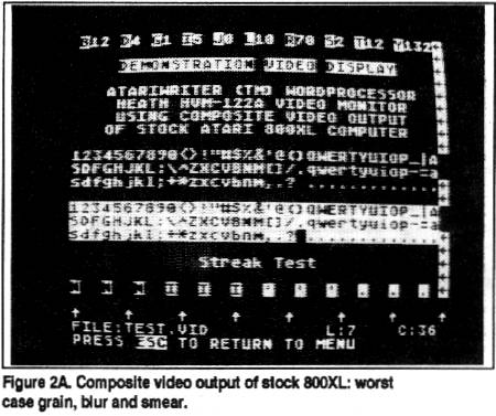
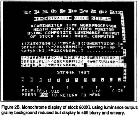
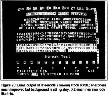
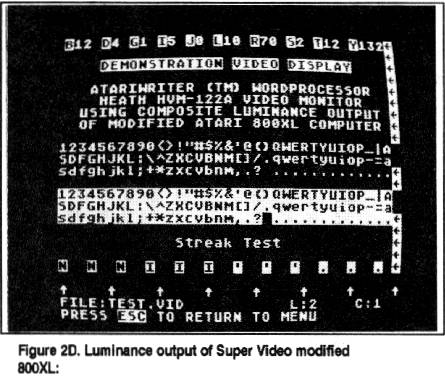
Figure 2 demonstrates in actual screen photos the various stages of video quality. These photos lose much detail in print, but even so you can see a big difference between 2A and 2D. Study these photos with a magnifying glass: the details should still be visible (I hope!). If your XL video looks like 2A, 2B, or 2C, and you'd like it to look like 2D, read on! (You 130XE folks will have screens that look like 2C; see Charles Cole's "Super Video for the XE" elsewhere in this issue if you want to upgrade your XE video.)
Super Video 2.0 For the 800XL
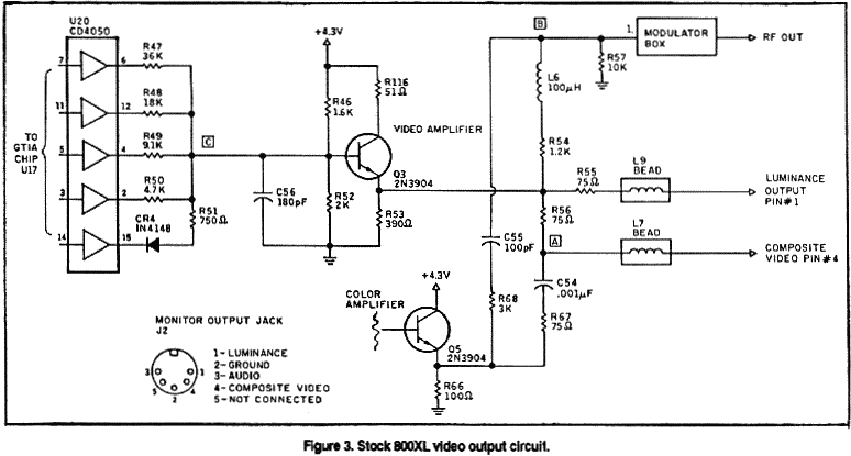
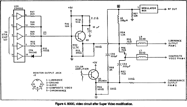
We'll do S-V 2.0 first; it's the easiest of the upgrades and yields spectacular results. You might elect to stop after doing S-V 2.0, since going further with 2.1 brings diminishing returns for more work. I guess I need to make a disclaimer here: if you try any of these mods and botch it, tough krinkles. The Alchemist, Staff and Publisher of AC won't be responsible for people who mangle their machines (or themselves) trying to do this stuff. You'll need resistors, capacitors, heat-shrink tubing, and a panel-mount SPST mini toggle switch, all available at Radio Shack. Buy the resistor assortment pack #271-312: it contains all the resistors you'll need in exactly the proper wattage and physical size, with plenty left over for future hacks. Figures 3 and 4 show the "before and after" schematics. The schematic of Fig. 4 essentially represents the upgrade as it will appear in all three XL machines. Only the component designations will differ.
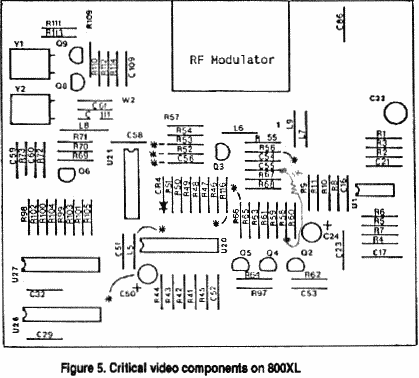
OK, let's get our hands dirty. Remove the six screws from the bottom of the case and separate the case halves. Remove the motherboard fastening-screws, and wiggle the board free of the case. Make sure you discharge yourself to some large (preferably grounded) metal object before removing the motherboard RF shields, and handle it only by the exposed broad foil ground plane strip around the edges. Place the board on a conductive surface (damp newspapers will suffice), and orient it according to the diagram in Fig. 5.
By The Numbers...
Study Figures 5-7 and refer to them for the following steps:
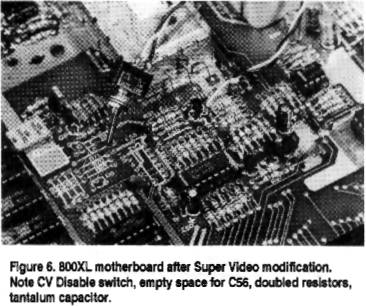
Step 1. Locate resistor R53. It will be either 390 ohms (orange-white-brown-gold) or 100 ohms (brown-black-browngold). Solder a resistor in parallel with R53 as follows: If R53 is 390 ohms, solder a 100-ohm resistor (brown-black-browngold) on top of it in parallel (see Fig. 6); if R53 is 100 ohms, solder a a 330-ohm resistor (orange-roange-brown-gold) on top of it in parallel. (This restores the mono output impedance to the correct value.)
Step 2. Locate the 180pF glass capacitor C56 and snip it off the board with fine wirecutters. (This improves video highfrequency response.)
Step 3. Locate R116, a 51-ohm resistor (green-brownblack-gold). Solder a 2.2-ohm resistor (red-red-gold-gold) on top of it in parallel. (This improves output current flow to Q3, which is "starved" for current in Atari's original design.)
Step 4. Select a l0uF/16V tantalum capacitor and bend the leads outward. Notice one lead is marked with a (+) sign. Position this part above the board so the (+) lead touches the bottom of the R116/2.2-ohm combination while the (-) lead touches the top of R66. The leads are too long. Cut them off right where the leads contact the respective resistors, then solder the cap in place. (This improves Q3's transient response and filters noise from the supply line feeding the video output.)
Step 5. Locate R66, a 100-ohm (brown-black-brown-gold) resistor. Solder a 330-ohm resistor (orange-orange-browngold) on top of it in parallel. (This lowers the impedance of the color signal output to the correct value.)
Step 6. Now we'll install the CV Disable switch. The purpose of this switch is to enable composite video for users whose color monitor accepts composite video only. Those who use luma or luma-chroma interfaces should toggle the switch to disable composite video. A cleaner signal, free of color clocking interference that makes the screen background grainy, will be obtained. Cut two 8" lengths of wire and strip 1/4" insulation from one end of each. Solder the stripped ends of each wire to the two lugs on the switch. Twist these wires lightly as shown in Fig. 6. At the unattached ends, snip off 1" from one of the wires, then strip 1/4" insulation from the ends of both wires. Set the switch assembly aside temporarily.
Now locate R56 on the motherboard, a 75-ohm resistor (violet-green-black-gold). We want to desolder the left end of this resistor (DON'T cut it!). Get a good grip on the left end with needlenose pliers, then apply your soldering iron to the joint at a 45-degree angle so it firmly contacts both the resistor lead and the solder pad. Allow sufficient time for the joint to heat up-about 10 seconds, the solder will start to bubble. With the iron still in place, pull up smoothly but firmly with the pliers: the resistor should come up easily. If it doesn't, allow a good 5 minutes for everything to cool down, then try again.
Once the left end of R56 is free, use the needlenose pliers to form the free lead end into a loop. Then bend the resistor into a vertical position supported by the end still soldered to the board. Clear the vacated hole of solder. Now retrieve the prepared switch assembly and solder the longer wire to the vacated R56 circuit board hole. Solder the shorter switch wire to the loop at the top of R56.
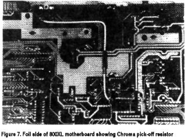
Step 7. Now we'll install the chrominance pick-off resistor. Select a 100-ohm resistor (brown-black-brown-gold), and to one end of it apply a length of insulation (stripped from wire) leaving only 1/8" of the lead exposed. Cut a 5" length of wire and strip 1/4" insulation from each end, then solder this wire to the uninsulated end of the resistor. Now experiment a little to find the smallest diameter heatshrink tubing that will fit over both the solder bulge and the resistor body, then snip off a length sufficient to cover the bare lead from the resistor body to the solder junction plus an extra 1/4" to overlap both ends. Slip the tubing into place, then warm it by holding the assembly 1/4" above your hot soldering iron while slowly rotating it for even heating. The tubing will contract to make a neatly insulated assembly (see Fig. 7). DO NOT use tape to insulate this resistor!
Solder the short end of the prepared resistor to the junction of R67-R68 on the foil side of the board. Solder the other end to pin 5 of the monitor jack, routing the wire through the gap between the ground plane foils as shown. Keep the wire close to the board. I later added a dab of hot-melt glue at the bend in the wire to secure it in place.
Step 8. On the rear panel of the case, at a point 1" above the bottom of the panel and midway between the monitor jack and the TV output jack, drill a hole for mounting the composite video enable/disable switch. The exact size of the hole depends on the diameter of the mounting stem of the switch. This completes the S-V 2.0 modification for the 800XL.
800XL S-V 2.0 Checkout
Place the bare board on a clean insulated surface (formica kitchen tabletops work well) and attach the power supply and video cables (a good monochrome monitor with luma connected is preferred here). Turn on the power (yes, the 800XL boots up fine without keyboard or shields installed). You should see BASIC's "READY" notice and cursor appear on your screen, brighter and clearer than ever before. Adjust the monitor's brightness and contrast controls so you can see the entire display, including the background. Work the CV Disable switch back and forth as you study the screen background. You should see a grainy background appear and disappear as you toggle the switch. Some monitors reveal this better than others, and it's harder to see if the focus control on your monitor is out of adjustment. On color monitors you might not see it at all.
If you're satisfied with your accomplishments to this point and don't wish to go further, reattach the RF shields to the board (route the switch wires out near the RF modulator), reinstall the board, fasten the switch to the rear panel, and close up the case. However, if you aren't afraid of more work and would like to push video performance to its very limit, keep that iron hot and move on to Super Video 2.1!
S-V 2.1 For The 800XL
If you have a RAMBO or other memory upgrade card installed, unplug it and keep it out of the way. Refer to Fig. 5 for the following steps:
Step 1. Locate 820uH inductor L5, usually a green-colored component that looks like a resistor with gray-red-brownsilver bands, directly in front of the 4050 chip U20. Desolder or snip out this part, then clear the vacated board holes with a solder sucker. Select a 2.2-ohm resistor (red-red-gold-gold), solder it in place of L5, and snip off the excess lead length. (This improves current flow to the entire video circuit.)
Step 2. Locate electrolytic capacitor C50 (10uF/10V): it's adjacent to the L5 inductor you just replaced. Desolder this capacitor and clear the vacated holes of solder. Replace C50 with another electrolytic capacitor of at least 100uF/10V rating. Radio Shack parts vary considerably in their physical dimensions, so when you're shopping be sure to examine all the parts packages in the range of 100 or 220uF of radial-lead electrolytics on the shelf in the store. Select whichever gives the largest uF value in the smallest physical size. I was able to squeeze in a 220uF unit and still didn't have trouble reinstalling my RAMBO board. (Restores AC filtration lost by removal of L5.)
Step 3. Locate 2K resistor R53 (red-black-red-gold) directly to the left of Q3 on the motherboard. Remove this resistor and replace it with a 2.7K resistor (red-violet-red-gold). (Improves color saturation slightly.)
Step 4. Solder a 1K resistor (brown-black-red-gold) from the right side of 100pF capacitor C55 to the bottom end of 6.2K resistor R58 (blue-red-red-gold). This resistor has to traverse about 1.5" of board space, so don't trim the leads. Mount it about 1/4" above the board on the component side, bending the leads down at the specified contact points. This resistor provides negative feedback around the color amplifier Q2-Q4-Q5. The effect is subtle, but it improves saturation a little and reduces color shadows somewhat.
This completes Super Video 2.1 for the 800XL. You'll probably find it necessary to reduce your display brightness controls when you perform your checkout, as the video signal is now stronger than it was with S-V 2.0. Check out the improvement on a color monitor if available before you close up the case. Use the luma-chroma interface to check proper operation of your chroma circuit wiring. For my color checkout I just stuck my Pole Position cart in the slot and booted up the bare board. Pole Position is nice because it's very colorful and self-starting. The display was wonderfully sharp and brilliant on a Commodore 1084 using the luma-chroma interface with composite video disabled. The Alchemist succumbed to several hours of game-playing after reassembling the computer. Unfortunately the crisp display didn't improve my driving, and those fiery crashes were all the more annoying for their clarity. Hrrrumph!
S-V 2.1 For The 600XL
For the remainder of this article I'm going to revert to a more truncated style of presentation in the hope of saving page space. Physically, S-V 2.1 in the 600XL is tedious, as boardspace alotted to the video components is rather a miniscule piece of real estate. Consequently the video circuitry is densely packed, and you'll have to mount most components vertically. With this upgrade we have a lot of labor to perform, since we'll be adding all the parts Atari swindled from us as well as replacing the bungled ones they installed.
The resistors, capacitors, and switch are all available at Radio Shack. You'll need three 2N3904 (MPS3904) transistors, also at Radio Shack (#276-2016). If the 3904 is unavailable you can substitue the 2N2222 (MPS2222), #276-2009. Don't take the specs and diagrams printed on the packaging too seriously: a 2N3904 and MPS2222A I purchased both showed the collector and emitter leads reversed on the package diagram. (I verified the leads on the actual parts with a click tester; they were correct. I long ago learned not to trust data furnished with the Rip-Off Shack's overpriced parts.) When installing these transistors, line up the flat side of the part with the flat side in the outline screened on the board.
You'll also need a 5-pin DIN board-mounted socket: that's a problem. These sockets are used in all IBM computers and are available dirt-cheap at every electronics outlet in the world. Except Radio Shack. Best Electronics sells them for $1.00 apiece. The problem is that no mailorder parts vendor wants to bother with an order for a single part that costs less than a buck. You'll have to be creative. Band together with friends or your usergroup and buy a whole bunch of them, or combine your order with other items. Perhaps some shrewd operator will stock up on them and offer them to AC readers through the Swap ads in the back of this magazine.
Refer to Fig. 8 for the following steps:
Step 1. Desolder and clear all the board holes for the following components:
| C111 |
J7 |
Q8 |
R128 |
R131 |
R134 |
R137 |
| C112 |
L12 |
Q9 |
R129 |
R132 |
R135 |
R138 |
| C113 |
Q7 |
R124 |
R130 |
R133 |
R136 |
R139 |
C109, C110, C115, L14, R59, R123, R127, R140, channel selector switch
Step 3. Install the following components at the indicated locations:
| Part |
Value |
Code/Mark |
Location |
| Blank space |
- 0 - |
- - - |
C109 |
| Capacitor,
ceramic |
100pF |
101 |
C110 |
| Capacitor, ceramic | 5pF |
4.7 or 5 |
C111 |
| Capacitor, ceramic | .001μF |
102 |
C112 |
| Capacitor, ceramic | 100pF |
101 |
C113 |
| Capacitor, rad.
elect. |
220μF/16V |
220/16 |
C115 |
| Switch (1) |
SPST |
- - - |
L13 |
| Resistor |
2.2 ohms |
red-red-gld-gld |
L14 |
| Transistor |
2N3904 |
2N(MPS)3904(2222) |
Q7 |
| Transistor | 2N3904 | 2N(MPS)3904(2222) | Q8 |
| Transistor | 2N3904 | 2N(MPS)3904(2222) | Q9 |
| Resistor | 1.5K |
brn-grn-red-gld |
R59 |
| Resistor (2) |
75 ohms |
[brn-grn-brn-gld]x2 |
R123 |
| Resistor (2) |
75 ohms |
[brn-grn-brn-gld]x2 |
R124 |
| Resistor | 2.2K |
red-red-red-gld |
R127 |
| Resistor (3) |
6.2K |
[orn-blk-red-gld]x2 |
R128 |
| Resistor | 1K |
brn-blk-red-gold |
R129 |
| Resistor | 2.2K |
red-red-red-gld | R130 |
| Resistor | 1K |
brn-blk-red-gold | R131 |
| Resistor | 1K |
brn-blk-red-gold | R132 |
| Resistor | 3.3K |
orn-orn-red-gld |
R133 |
| Resistor | 10K |
brn-blk-orn-gld |
R134 |
| Resistor | 220 ohms |
red-red-brn-gld |
R135 |
| Resistor (2) |
75 ohms |
[brn-grn-brn-gld]x2 | R136 |
| Resistor (2) |
75 ohms |
[brn-grn-brn-gld]x2 | R137 |
| Resistor | 3K |
orn-blk-red-gld |
R138 |
| Resistor (4) |
4.7K |
yel-vio-red-gld |
R139 |
| Resistor | 1K |
brn-blk-red-gold | R140 |
Notes :
(1) Two 7" lengths of stranded wire, lightly twisted, from switch lugs to L13 holes. (CV disable switch)
(2) Synthesized value: two 150-ohm resistors in parallel.
(3) Synthesized value: two 3K resistors in series.
(4) Designated R141 in Atari diagrams (schematic error).
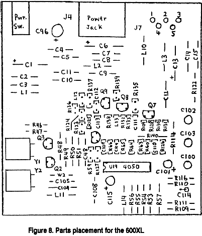
Step 3. On the foil side, cut the foil connection between pins 2 and 5 of J7.
Step 4. Install the 5-pin DIN jack on the component side of the board. Depending on the particular style of unit, it might be necessary to file down the two front pins to get them in the holes. Solder all the pins, including the two front ones.
Step 5. Now we bring out the luminance signal to the jack. Twist together two 150-ohm resistors (brn-grn-brn-gld), solder the leads together, and place insulation (removed from wire) over all but 1/8" of the exposed lead length on both sides. On the foil side of the board, solder one end of this part to the junction of R123-R124 and the other end to pin 1 of the output jack J7. Depending upon lead length, you might have to add a short length of insulated wire to one end of this part. Mine barely made it without adding extra wire.
Step 5. Now we'll bring out chroma to the jack. Select a 100-ohm resistor (brn-blk-brn-gld) and place insulation (removed from wire) over all but 1/8" of the exposed lead length on both sides. On the foil side of the board, solder one end of this part to pin 5 of output jack J7, and the other end to the emitter lead of Q9. This lead is on the left when you look at Q9 face-on.
Step 6. On the bottom half of the RFI shield, locate the square hole where the channel selector switch used to be. Cut out all the metal above this hole, extending to a distance of about 2mm on either side of the hole, and all the metal below the hole down to the bend. You'll end up with a squarelooking version of the big notch already present for the adjacent power supply jack.
We have to cut another notch for the CV Disable switch. Viewing the RF shield from the rear, cut a notch 18mm wide commencing at a point 3mm to the left of the hole already present for the RF output jack. This notch should extend all the way to the bend in the metal. You'll lose a shield mounting tab, but that doesn't matter.
Cutting these notches isn't easy. I used a Moto-Tool equipped with an emery cutting wheel to do a neat job, and I filed down burrs and sharp edges with a fine Swiss file. Tin snips might also work but would probably warp the metal. Heavy-duty wirecutters might also suffice, though they might not be much good for anything else when you're done. Sheet metal is a pain.
Step 7. Now we have to make holes in the rear panel outer case, starting with the hole for the video jack. Measure off a point exactly 21mm to the left of the leftmost edge of the power connector hole. Make an indent there to start your drill bit, then drill a 3/4" hole. If all goes well you'll completely obliterate the existing rectangular opening where the channel selector was. In my experience it's better to have an opening too large than too small. Square off the edges of the hole with a round Swiss file. On my unit I filed off the "2 - CHAN - 3" lettering, which is now meaningless.
Now for the CV Disable switch hole. At a point 25mm from the bottom of the rear panel, and 13mm to the left of the leftmost edge of the RF modulator hole, drill a hole for your switch. The diameter of this hole should be just slightly larger than the mounting stem of your switch (I used a 3/8" bit). If you follow these instructions exactly, everything should fit perfectly when you reassemble the case.
Checking Out The S-V 2.1 600XL
Boot up the bare motherboard with your favorite monitor as described earlier for checking out the mod on the 800XL. After upgrading my 600XL I was pleased to observe a crisp display in both mono and color whose characteristics were identical to the results I obtained with the 800XL, including the function of the CV Disable switch. After you're satisfied everything is running OK, reassemble the shields and case and close it up.
Those of you who still want to use the TV interface on your 600XL might be concerned about the loss of the channel selector switch. It's actually still there: removing the switch is equivalent to leaving the selector permanently set on the Channel 3 position (I haven't verified that). If you're really very fussy about this you can always run some wires from the channel selector switch holes in the vicinity of J7 out to another SPST switch mounted on the rear panel-if you can find room for it! Having gone to all this trouble installing the electronics for interfacing my 600XL to a nice crisp monitor, I don't give a hoot about the TV interface any more.
Perspectives On 1200XL Video
Despite the abundance of extra parts in the 1200XL video section, it turns out the basic design of the 1200XL video amplifiers isn't much different than the ones in the 800XL and 600XL. In all three machines color is handled by a group of three transistors, while the baseband monochrome/composite output is a separate single-transistor circuit. All these transistors are 2N3904 types. The table below summarizes the schematic designations of these transistors and briefly describes their functions:
| Function | 600XL | 800XL | 1200XL |
| 1st color amp | Q7 |
Q2 |
Q19 |
| 2nd color amp | Q8 |
Q4 |
Q8 |
| Color output | Q9 |
Q5 |
Q7 |
| Mono/CV output | Q6 |
Q3 |
Q11 |
What sets the 1200XL apart from the other XL machines is an extra three-transistor circuit (Q16-Q17-Q18) whose input connects to the color sync signal at GTIA pin 25. The output is emitter-coupled to the color amp circuit via a diode (CR19) to Q19. It took me a while to dope out what this was for, but once I caught on my imagination was gripped in a spell of astonished wonder. This extra little circuit boosts color saturation. And The Alchemist is here to tell you its effect amounts to video magic. If Atari had included this extra 25-cents' worth of parts in all its 8-bit machines, and hadn't squandered it by butchering the rest of the video circuitry, the Atari 8-bit could have blown away the competition hands-down. Especially for color graphics and games!
Curing the video defects in the 1200XL was no easy task: the gremlins were well-entrenched with multiple lines of defense, and they fought The Alchemist tooth and nail every inch of the way. But, as General Grant discovered in the American Civil War, the secret of victory lay in lessons learned from the battles fought. That secret is to achieve a balance between three conflicting elements of the color output, which are: 1.) color saturation; 2.) color shadows; and 3.) sharpness (signal strength and bandwidth). The main rule of the game is: "Anything you do to improve one of these elements will necessarily degrade performance of at least one, and probably both, of the other two." Insofar as the monochrome amplifier plays a key role in achieving the best color display, improving the color display automatically results in optimized monochrome performance.
My philosophy was to tolerate a certain amount of color shadows while maximizing sharpness and saturation. This approach provides maximum benefit for both mono and color users. Color shadows don't affect the monochrome display at all, while the optimized signal provides the best possible screen sharpness for text. On color displays, the eye tends to be more forgiving of object shadows if the picture is sharp and clear and full of brilliant color. Object shadows in the color display seem to me a video artifact that varies according to the particular combination of colors on the screen, being absent with some combinations and more noticeable with others. The S-V 2.1 upgraded 1200XL still exhibits some color shadow artifacting, but I'm gambling most people won't notice it while they're playing a fast-moving videogame on a crisp, vividly colored screen. In short, you game freaks will have a field day playing color games on a 1200XL upgraded to S-V 2.1XL using a luma-chroma interface.
S-V 2.1 For The 1200XL
OK, let's do it. Refer to the board layout diagram in Fig. 9 for the following steps.
Step 1. Cut out the following components from the motherboard:
| C60 |
CR20 |
| C62 (1) |
R25 |
| C101 (1) |
R28 |
Step 2. Carefully desolder capacitors C103 and C104. One of them will be re-used. You don't have to clear the vacated board holes of solder.
Step 3. Desolder the following components from the board and clear the vacated board holes of solder:
| C63 |
L15 |
R145 (1) |
| C99 |
R21 |
R181 |
| C115 |
R44 |
R187 |
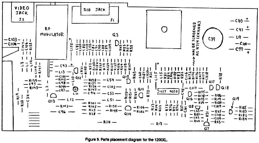
Step 4. Install the following components at the indicated locations:
|
Part |
Location |
| Capacitor, glass ceramic,.001uF (1) | C63 |
| Capacitor, electrolytic, 220uF/16V (2) | C99 |
| Jumper wire | C115 |
| Resistor, 100 ohms (brn-blk-brn-gld) | L15 |
| Resistor, 1.5R (brn-grn-red-gld) | R21 |
| Resistor, 75 ohms [brn-grn-brn-gld]x2 (3) | R44 |
| Resistor, 10K (brn-blk-orn-gld) | R145 |
| Jumper wire | R181 |
| Resistor, 2.7K (red-vio-red-gld) | R187 |
Notes :
(1) Use one of the caps removed in Step 2 above.
(2) Use either a radial- or axial-lead unit; axial is preferred if you can find one that fits.
(3) Synthesized value: two 150-ohm resistors in parallel.
Step 5. Select a 120-ohm resistor (brn-red-brn-gld). Bend the leads and cut to an appropriate length, and solder this resistor in parallel on top of R23 on the component side of the board.
Step 6. Prepare a synthesized 75-ohm resistor by twisting two 150-ohm resistors (brn-grn-brn-gld) together in parallel and soldering the leads together. On the component side of the board, solder one end of this part to the top of R22 and the other end to the bottom of C48.
Step 7. Select a 120-ohm resistor (brn-red-brn-gld). Trim one lead to a length of about 1/2". On the component side of the board, solder the short lead of the 120-ohm resistor to the top of R24, and allow the 120-ohm resistor to stand vertically. Now, carefully desolder the bottom end of R24 and clear the vacated hole of solder. Stand up R24 vertically alongside the 120-ohm resistor, and solder the free ends of the two resistors together. You should have at least 1/2" of lead length remaining at the free end. Form this extra length into a small loop about 3mm in diameter and trim of any excess.
Step 8. Cut two lengths of stranded wire 10" long and strip 1/4" of insulation from both ends of each. Select a panelmount SPST switch and solder one end of each wire to each lug. Twist these wires lightly through their whole length. Solder one end of one wire to the loop at the top of R24 you made in Step 6 above. Solder the other wire to the hole in the circuit board vacated by the bottom end of R24.
Step 9. Select a 330-ohm resistor (orn-orn-brn-gld). Bend and trim the leads appropriately, then solder this part in parallel on top of R45 on the component side of the board.
Step 10. Select a 100-ohm resistor (brn-blk-brn-gld). Place insulation (removed from wire) on both leads, leaving only 1/4" bare lead exposed. Now cut a length of insulated wire 10" long and strip 1/4" insulation from both ends. Solder one end of this wire to one lead of the resistor and insulate the joint with heatshrink tubing (NOT tape!). Now turn the 1200XL motherboard over and examine the foil side. What you want to look for are "channels" created by rows of resistors on the component side: we'll use these channels to route the chroma signal wire to the output jack. There are four of them; it will help to mark their location with a pencil. The first "channel" begins with R43 and ends with R186. The second begins with CR18 and ends with R153, the third at R107 and ends with CR21, and the fourth at R155 to end at C147.
Now locate R45 on the foil side of the board directly in front of Q19. On the foil side, solder the resistor end of the resistor-wire assembly to the end of R45 that's furtherest away from Q19. Bend and shape the resistor leads and wire so the resistor body lies in the middle of "channel 1", makes a right-angle bend to run down the middle of "channel 2" and a 45-degree bend to run down the middle of "channel 3", followed by a final 45-degree bend to run down the middle of "channel 4". This will bring the wire out close to the jack. Route the end of the wire through the break in the ground foil plane and solder the bare end to pin 5 of the output jack. This pin is easily located because it's the only one without a foil trace connected. Place three or four tiny dabs of hot-melt or silicone adhesive along the path of the wire to hold it in place on the underside of the board.
Step 11. Drill a hole in the rear panel of the bottom case directly above the channel selector switch, using a bit of appropriate size to match the mounting stem of your switch. Mount the CV Disable switch here after routing the wires out through the crack between the RF shield and the modulator box. This completes the modification.
1200XL Checkout and Wrapup
Boot up the bare 1200XL motherboard (preferably with a cartridge installed) with a monitor attached as described for the 800XL and 600XL upgrades. Observe the effect of the CV Disable switch, most visible on a monochrome monitor. (The effect of the switch is usually not observable on color monitors.)
If you're using a color display with a CV or luma-chroma interface, you'll notice how sharp and brilliant the colors now are. If you desolder one end of CR19 and lift it from the board, you'll have a color display that's identical to the color displays generated by the other S-V 2.1-upgraded XLs: sharp and clear, but with less vivid colors. Removing CR19 disconnects the saturation boost circuit; I think it looks better with CR19 left connected. Perhaps some enterprising hardware entrepreneur out there will make up a little circuit board kit for retrofitting Atari's saturation boost circuit to the other XLs; the electronic parts cost less than 50 cents.
Monitors
For testing purposes throughout this project I used the following monitors: Apple A2M2010 green-screen monochrome (luma interface), Commodore 1902 and 1084 (luma-chroma and CV interfaces), Amdek Color 300 (luma-chroma and CV), Magnavox 1CM136 (luma-chroma and CV), and a Magnavox RD0510 5" portable color TV with direct video input (luma or CV interface). The Apple monochrome monitor of course gave the cleanest display: crystal-clear and razor-sharp using the CV Disable switch. Performance among the various color displays varied tremendously. The Commodore monitors, with their fine dot-pitch, gave the sharpest color images, while I judged the Magnavox 1CM135 slightly less sharp than the Commodores. The coarse dot-pitch on the Amdek rendered poor resolution, but color saturation on the Amdek is superb even with the pallid color output of the upgraded 600XL and 800XL. Performance on the little Magnavox TV didn't compare to the monitors due to the tiny screen and really coarse dot-pitch. You could run color games on it for demo purposes. Using only the luma output and turning off the color controls, you could do 40-column AtariWriter wordprocessing on it if you don't mind the tiny letters.
Coda
While I was writing up this article a long-awaited 1450XL finally arrived. With considerable excitement I connected it to my test monitors and fired it up. Horrors!! The display was as bad as a stock 1200XL! With no schematics, board diagrams, or manuals of any kind, and an opaque circuit board that you can't follow traces on by holding it up to strong light (the 1450XL employs a multilayered board), reverse-engineering the video circuits is a formidable task. I took time away from this article to hack it. I only got bits and pieces, but that was enough. The mono circuit has a 390-ohm output impedance (groan!), and there's a capacitor sucking away all the high-frequency response from the mono output, the mono output is full of color clocking trash, I can't find the chroma... sheesh! The long arm of the Sunnyvale Butchers reached out to poison even the products that never made it to market.
Thanks for the tainted legacy, Atari.
