THE DEGAS ELITE
IMAGE GENERATOR
IMAGE GENERATOR
by Robert M.
Birmingham and Richard C. Leinecker
If you're a programmer who has experimented with computer animation, you know that one of the least enjoyable parts of the process is defining the bit-mapped images you wish to animate. This is usually done by drawing the image on a piece of graph paper, then translating the image into numbers that the computer can understand.
Besides being time-consuming, one mistake may mean that you have to start over from scratch. If this sounds familiar, we can sympathize, since we've done the same thing more times than we'd like to admit! Faced with doing this "one more time" and with our patience worn thin, we figured there had to be a better way. So we locked ourselves away and set out to find the solution. Several days later we emerged with The DEGAS Elite Image Generator.
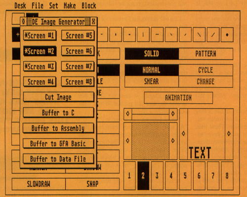
The DEGAS Elite Image Generator, or The Generator for short, is a GEM desk accessory that uses DEGAS Elite's ability to communicate with specially written accessories. Using this communication system, The Generator lets you cut sections from DEGAS Elite pictures, in any resolution, and save them to a disk file or send them to your printer.
The program can output your images as source code for C, assembly and GFA BASIC, as well as output your images as a special data file.
Getting
Started
Before you can use The
Generator, you need to copy the GENERATR.ACC file to the drive
you normally boot from (this is usually Drive A: for floppy-based
systems or Drive C: for hard-disk-based systems). Now, reboot your
computer so it loads the accessory; then run DEGAS Elite. You won't be able to
use The Generator from the
GEM desktop, or from any other program, because it was written
specifically for DEGAS Elite.Once you have DEGAS up and running, load a picture from disk so you can work through the following example. From the main menu screen of DEGAS, select the "The Generator. . ." item from the Desk drop-down menu. The Generator's window will then pop up on the screen.
The
Screen Buttons
At the top of the window you will see eight buttons
labeled SCREEN #1 through SCREEN #8. These buttons correspond to the
eight screens that DEGAS supports.
Clicking the mouse on one of these buttons allows you to select the
screen from which you will be cutting an image. If you don't have
enough memory to support the maximum of eight screens, The Generator will show the
unavailable screens as disabled (lightened text), and you won't be able
to select them.You may have noticed that when you first selected the "The Generator. . ." menu item, there was a short pause before the window actually appeared. This is because the accessory is checking each DEGAS screen for picture information. If a screen has data in it, an asterisk will be put in front of the corresponding SCREEN # button. Otherwise, a blank space will precede the SCREEN # button.
The
"Cut Image" Button
Once you have a picture in memory, you are ready to
cut an image. First, make sure the SCREEN # button selected (the one
that is highlighted) indicates the screen containing your picture.
Next, click the mouse on the "Cut Image" button. Your picture will be
displayed, along with a pair of rubberbanding lines. If you hit a key
while these lines are displayed, you will be returned to the main
screen.Move from where the two lines meet to the top-left corner of the section you want to cut, then press the left mouse button. The rubberbanding lines will now change to a rubberbanding box. You may cancel the rubberband box and go back to the rubber-band lines by pressing any key. Adjust the box's size by moving the mouse, then click the left mouse button to select the lower-right corner of the section you want to cut.
To help you select the exact position and size of the box you want, its coordinates, width and height are printed on the screen. Note that when you are specifying the box, the area under the rubber-banding box is included as part of your image. Once you've selected an image, you will automatically be returned to the main DEGAS screen.
The
Buffer Buttons
If you haven't cut a section from a DEGAS picture, these four buttons
will be disabled and you won't be able to select them. However, if you
followed the instructions for the "Cut Image" button (see above) and
have cut an image, these buttons will be selectable. You can now save
the image as source code for C, assembly and GFA BASIC, or as a
specially formatted data file that you can load into your program at
runtime. Select the button corresponding to the type of data you want
to save.The buttons labeled "Buffer to C," "Buffer to Assembly" and "Buffer to GFA BASIC" let you save the image rectangle you've selected as source code for the respective language. Since the main difference between these buttons is in the output file they generate, the following description applies to all of the buttons. However, any differences will be noted.
When a button is selected, you will be asked if you want to save a "mask" image along with the image. A mask is a special image that is used to clear out the screen area where the main image is going to be placed. This is similar to using a cookie cutter to remove a shape from a sheet of dough. If the mask isn't used, there will be a conflict between the image and whatever is at the same screen location when the regular image is placed on the screen. This results in your image having the wrong colors. We will cover masks in more detail later on in the article.
You will next be asked to enter the name you want to give the source data. For the C selection, this will be used as the name of an array, pre-initialized to contain your image data. For the assembly selection, the name will used as a label marking the beginning of a series of ".dc.w" directives containing the image data. For the GFA BASIC selection, the name will be used as a label marking a series of DATA statements. These DATA statements not only contain your image data, but also contain a special header block which makes it easy to use GFA BASIC's built-in PUT image command to manipulate the image (see the GFA BASIC example program on this month's disk).
If you chose to save the mask image data, The Generator will append the string "_mask" to the name you entered, then save the mask image source data in the same manner as the regular image data. For example, if you entered the string "data" as the name for the image data, then the program will save the mask data with the name "data_mask."
If you use The Generator to save several images, you might lose track of the names of the images you've already saved. Because of this, a list of the names you've already entered is displayed whenever you're asked to enter a new name.
Last, you will be asked if you want to send The Generator's output to the printer or to a disk file. If you choose the printer for output, the data will be sent immediately. However, if you opted to save the source data to disk, a file selector will be displayed to let you choose the name for the file.
If you try to save the source output to a file that already exists, you will have the option to replace it or append the source output to the existing file. This feature allows you to easily build a file that contains multiple source images to be included in your program.
The
"Buffer to Data" Button
This button makes The
Generator even more flexible, especially if the set of languages
supported doesn't include the one you normally use to write your
programs. Basically, this option saves the image data as a special file
that can be loaded into your program when you run it.When saving your data, The Generator produces a file with a specific format. The first word of the file indicates the number of images it contains. The image count does not reflect the presence of any masks in the file; this is contained in a block of information called a header, which precedes every image saved to the file.
The first word in the header contains the image resolution in the low byte, and a flag in the upper byte ($0100) indicates the presence (set) or absence (not set) of a mask image. The next two words are the image width and height, respectively. The last piece of information in the header is a long integer indicating the number of bytes in the image. This long integer only represents the size of the image; if a mask is present, it has the same number of bytes and immediately follows the data for the image. The mask does not have its own header since the image and mask have the same attributes.
Using
Images in Programs
Now that you know how to use The Generator to output the source
code for your image, you may want to write a program that makes use of
this data. We will get to this momentarily, but before you can delve
into the programming, you need to know how the Atari ST handles
graphics.The ST supports three different formats for the 32,000 bytes it uses for screen memory: low resolution, which supports 320 pixels x 200 pixels with 16 colors; medium resolution, which supports 640 pixels x 200 pixels with four colors; and high resolution which supports 640 pixels x 400 pixels with two colors. While knowing the dimensions of the screen is important, you also need to know how the ST's screen-memory information is arranged. Unfortunately, this arrangement can be confusing because it varies depending on the current resolution.
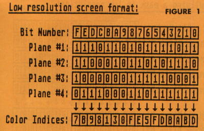
In the low-resolution mode, the memory used for the screen display is separated into four sections, commonly called bit-planes. To determine the color of any pixel, a bit is taken from the same position in each bit-plane and combined to form a color index for that pixel. The screen-memory information is arranged such that the first four words (a word is 16 bits) represent planes one through four and thus denote the first 16 pixels on the screen (located in the upper-left corner). The next four words denote the bit-planes for the next 16 pixels on the screen, and so on, for the remainder of screen memory. This scheme is known as an interleaved bit-plane format because all the data is mixed together.
Since four bit-planes are used, 16 color-index values are possible. It is important to note that the color-index value doesn't represent a fixed color, such as red or yellow; instead it is used to access a color-palette table of 16 values. The values in the colorpalette table hold the red, green and blue (RGB) content for the pixel's color.
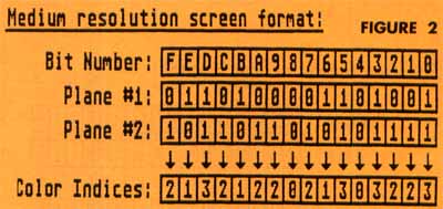
In the medium-resolution mode the screen memory is still separated into bit-planes. However, this time there are only two bitplanes. Therefore, a pixel is made up of two bits, which gives four different color-index values. The color-palette table is accessed in the same manner as it is for low resolution, but only the first four entries in the table are used.
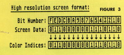
The high-resolution mode is the easiest to understand because only one bit-plane is used. This results in only two possible colorindex values for any pixel. Also, now only the first two palette-table entries are used.
Refer to Figures 1, 2 and 3 for examples of how the color indices are formed in each resolution.
Now that we've covered the basics of the Atari ST's screen format, we can now put an image on the screen. For the following example we'll be using the C language to describe the process.
The first step is to define the data you want to display. For example, assume we have created a 16x16-pixel image and given it the name "shape." The Atari ST's operating system supports many different types of functions to aid the programmer. Fortunately, one of these functions enables us to move blocks of memory from one location to another in several ways. The function we will use to copy our image is vro_cpyfm(). Here's an example of what it looks like in C:
vro_cpgfm(
handle, node,
pxyrray, &image, &screen );
pxyrray, &image, &screen );
As you can see, vro_cpyfm() requires several rather cryptic-looking arguments. Among these arguments are the addresses of two data structures called Memory Form Definition Blocks, or MFDBs for short. The MFDBs are used to hold information about the memory areas that we will be manipulating. The &image argument is the address of the MFDB for the image we want to copy (called the "source"), and the &screen argument is the MFDB for the area of memory to which we want to copy the image (called the "destination"). Although the MFDB structure is defined in the GEMDEFS.H header file, we have included it here for clarity:
typedef
struct(
long fd_addr; /* Address of image */
int fd_w; /* Width of image in pixels */
int fd_h; /* Height of image */
int fd_wdwidth; /* Width of image in words */
int fd_stand; /* Bit-Plane format */
int fd-nplanes; /* Nunber of bit planes */
int fd_r1; /* Reserved */
int fd_r2; /* Reserved */
int fd_r3; /* Reserved */
) FDB;
To declare our source and destination MFDDs in C, we simply do the following:
FDA
image, screen;
Now we need to initialize both of the data structures with the necessary information:
image.fd_addr
= shape; /* shape data
address */
image.fd_w = 16; /* 16 pixels wide */
Image.fd_h = 16; /* 16 pixels high */
image.fd_wdwidth = 1; /* Width of image in words */
image.fd_stand = 0; /* Interleaved bit-planes */
image.fd_nplanes = 4; /* Low Res has 4 bit planes */
image.fd_rl = 0; /* Reserved */
image.fd_r2 = 0; /* Reserved */
image.fd_r3 = 0; /* Reserved */
screen.fd_addr = Physbase(); /* Screen memory address */
screen.fd_w = 320; /* 320 pixels wide */
screen.fd_h = 200; /* 200 pixels high */
screen.fd_wdwidth = 20; /* Width of image in words */
screen.fd_stand = 0; /* lnterleaved bit planes */
screen.fd_nplanes = 4; /* Low Res has 4 hit planes */
screen.fd_rl = 0; /* Reserved */
screen.fd_r2 = 0; /* Reserved */
screen.fd_r3 = 0; /* Reserved */
Next, we need to specify the rectangular region within the source MFDB from which we want to copy and the rectangular region within the destination MFDB that we want to copy it to. This is done by setting up an array that contains the coordinates for the upper-left and lower-right corners for both the source and destination rectangles. For our purposes, we will be copying the entire 16x16-pixel area defined in the source MFDB to a 16x16 area somewhere in the destination MFDB. To do this, we first need to declare the array for the coordinates:
int
pxyarray[8];
Then, somewhere before we actually perform the vro_cpyfm() call, we need to initialize the array:
pxyarray[0]
= 0;
pxyarray[l] = 0;
pxyarray[2] = 15;
pxyarray[3] = 15;
pxyarray[4] = 100;
Dayarray[5] = 100;
pxyarray[6] = 115;
pxyarray[7] = 115:
pxyarray[l] = 0;
pxyarray[2] = 15;
pxyarray[3] = 15;
pxyarray[4] = 100;
Dayarray[5] = 100;
pxyarray[6] = 115;
pxyarray[7] = 115:
Finally, we have several options as far as the way the source image is combined with the destination image. One option is to have the source rectangle completely replace the destination rectangle. Or, we may perform logic operations between the two rectangles, such as ANDS, ORs, Exclusive ORs, etc. For our example, we will use mode 7, which tells vro_cpyfm() to logically OR the source rectangle onto the destination rectangle. As we will see in a moment, this will cause us some problems.
Assuming we have opened a graphics workstation and have our "handle" for the virtual workstation, we can now move the source rectangle to its location within the destination rectangle:
vro_cpyfm(
handle, 7, pxyarray,
&source, &dest );
&source, &dest );
The problem with using the OR mode is that if a nonzero pixel in the source rectangle is ORed with a nonzero pixel in the destination rectangle, the result is an undesired pixel value. For example, if a pixel in the source image is color 3 and the pixel in the destination image that it is ORed with is color eight, the resulting pixel value will be color 11. To alleviate this problem, we must have some way of clearing all the pixels in the destination rectangle that will be ORed with a nonzero pixel in the source rectangle before we copy the main image to the screen. This technique is known as bit-masking, or masking for short.
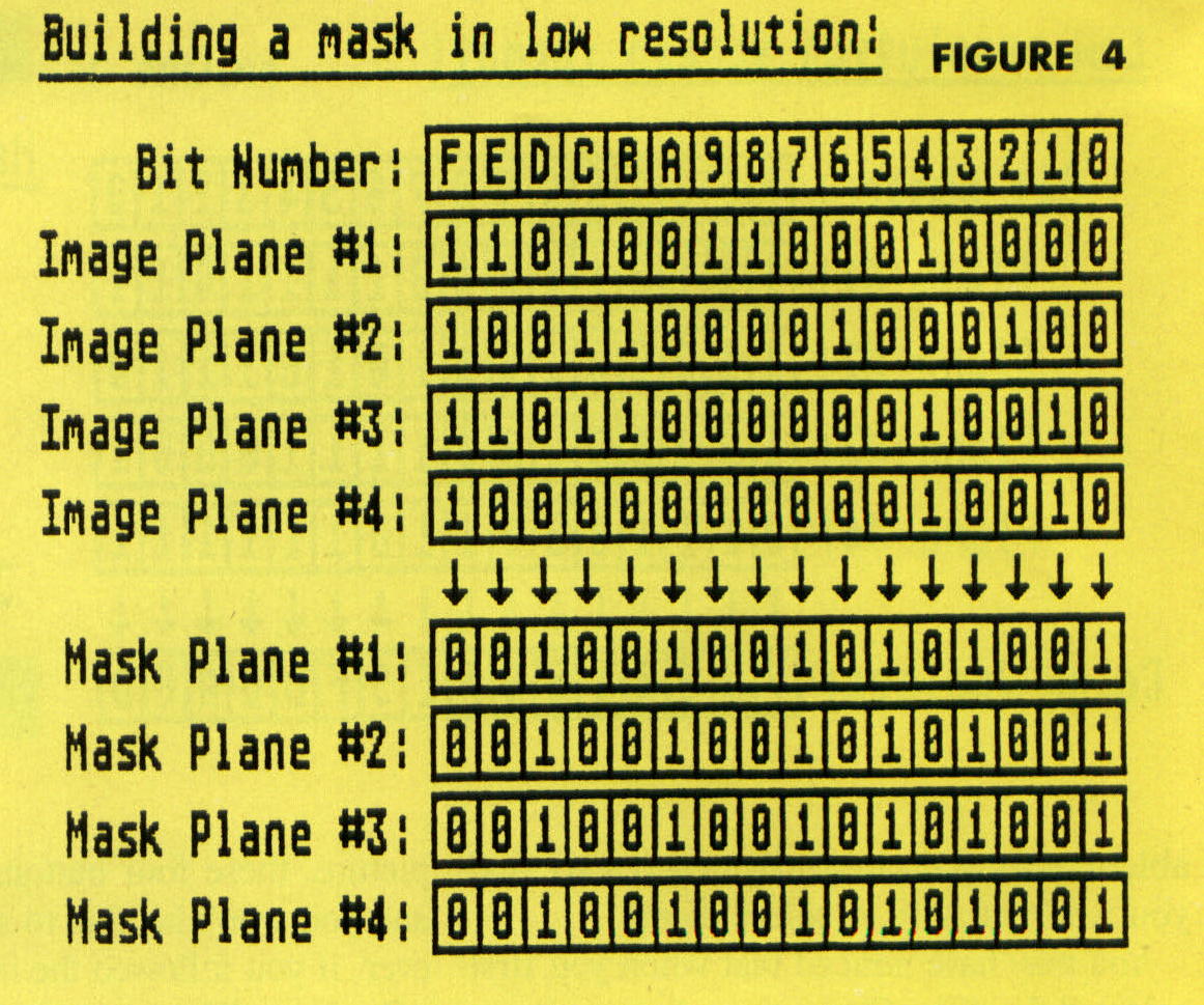
A mask is an image whose contents are derived from the primary image that you want to place on the screen. Fortunately, The Generator will output the mask information for you, but just so you know what's going on, the mask is made according to the following rules (also, refer to Figure 4):
(1) If the color of a pixel in the main image is not zero, then the color of corresponding pixel in the mask will be set to zero.
(2) If the color of a pixel in the main image is zero, then the color of the corresponding pixel in the mask is set to color 15. In other words, the corresponding bits in each of the four planes are set to ones.
Now that you know what a mask is, you may be wondering how to put it on the screen. In effect, you can do this in almost exactly the same manner in which you put the main image up in the previous explanation of vro_cpyfm(). The only difference is that you must AND it to the screen. Since the mask contains a color zero pixel for every nonzero pixel in the main image, the exact area that will be taken up by the main image will be erased. Also, since the mask contains ones for every zero pixel in the main image, those pixels will be left undisturbed!
To use the mask, first declare an MFDB for the mask:
FDB
mask;
Then, before copying the mask to the screen, initialize the MFDB:
mask.fd_addr
= mask_inage; /* mask data address */
mask.fd_w = 16; /* 16 pixels wide */
mask.fd_h = 16; /* 16 pixels high */
mask.fd_wdwidth = 1; /* Width of image in words */
mast.fd_stand = 0; /* Interleaved bit-planes */
mask.fd_nplames = 4; /* Low Res has 4 bit planes */
mask.fd_rl = 0; /* Reserved */
mask.fd_r2 = 0; /* Reserved */
mask.fd_r3 = 0; /* Reserved */
Notice that the mask's MFDB and the MFDB for the main image are almost identical. Also, since the source and destination rectangles we've already defined in the pxyarray (see above) are the coordinates we want, we can use the array for copying both the mask and the main image:
vro_cpyfm(
handle, AND, pxyarray, &mask, &screen );
vro_cpyfm( handle, OR, pxyarray, &source, &screen );
vro_cpyfm( handle, OR, pxyarray, &source, &screen );
We now have copied the mask and the image to the screen without the ORing problem.
About
the Examples
As we mentioned earlier, we have written some
example programs that show you how to use the image data saved by each
of The Generator's output
selections. The C language and the data-file demonstration programs
were written with Megamax C and use many of the same techniques
described in the vro_cpyfm()
tutorial above.The 68000 assembly demonstration was written with the Mad Mac assembler from. . Atari and uses a low-level Line-A operation to copy the image to the screen. While the Line-A example might be harder to follow than the other examples, the program is thoroughly commented, so you should be able to understand it if you're familiar with assembly language.
The GFA BASIC demonstration uses the header information at the beginning of the DATA statements to set up the information needed by the PUT conunand. Note that this header is not saved in the source code files for C and assembly; it is only available in GFA BASIC.
The DEGAS Elite Image Generator was written to save us the time and trouble of defining our bit-mapped images by hand. In fact, writing The Generator has already turned out to be time well spent, since we've used it to create images for several other programs we've developed. If you're a graphics-oriented programmer, we feel that it will prove to be a useful utility for you as well.
Robert Birmingham is 26 and lives in Miami. Although he has been programming for nine years, he remains thoroughly fascinated with computers. In his spare time he enjoys listening to music, building model rockets, juggling and stargazing.
Richard Leinecker is a geometry teacher at South Miami Senior High School. He's also a senior programmer/analyst at IntraCorp, Inc. He has programmed numerous pieces of entertainment software and has written several hardware-project books for the ST.