Real-World Interface
Real-World Interface is a hardware-software project that can control a wide variety of electronic equipment with your Atari. This BASIC program works on all 8-bit Atari computers of any memory size, with disk or cassette.
The idea of using a computer to control real objects always fascinated me. Last summer I decided that something had to be done about the problem of low humidity in my orchid greenhouse and my Atari turned out to be part of the solution.
If you don't have a greenhouse, stick around anyway. The first link between my Atari and my greenhouse is a simple relay that can be used for many different applications. And programming the Atari to operate it is really easy. Also, the real-time clock routine that I use for timing relay operations can easily be incorporated into other programs.
The conventional approach to my low-humidity problem would have been to use a humidistat to control a solenoid valve (operating on house current) to control water flow to misters or foggers. But there are other considerations here in Austin, Texas where high heat can be a serious problem. I had been searching fo some type of emergency system to cool the plants in case of power failure, and the best answer seemed to be drenching them in fog.
The problem was how to generate the fog with no electricity. At the same time I decided to install misters for humidity, I came across an ingenious battery-operated water valve. I knew immediately that I had found not only a means of solving my humidity problems, but also the key to making the elusive emergency system work.
This valve comes with a programmable electronic module to control when the water will be on. It was simple to remove the module--which is, of course, just an elementary computer--and connect the valve to a much more complex computer, my Atari. Originally, the valve could be set for a maximum of four time periods per day, with the shortest time period being one minute. But with the Atari, I can turn the misters on for just seconds, and I can do it as many times a day as I want.
Just as important, with this setup I can be sure the misters don't come on when they shouldn't. Orchids should not be wet when the temperature is too low, and they should always be dry by nightfall. A thermostat placed in the circuit between the valve and the Atari makes sure that the misters don't come on if the temperature is too low. And this program lets me choose the earliest and latest times for the misters to come on.
RELAY OPERATIONS
Finally, the circuit and program are set up so that instead of operating the relay to turn on the misters, as you'd expect, the relay shuts off the misters when it operates and turns them on when it releases. If the power fails and the Atari goes down, the relay releases and the misters stay on, providing some relief from the heat until power is restored. Then, because of the internal design of the joystick ports, the relay will operate automatically and shut off the water without needing a program to tell it to. And the greenhouse fans can start drying things off.
The first step in controlling the relay is to configure the joystick port-- the two jacks that the joysticks plug into. PORTA refers to Jacks 1 and 2. On the early Atari 400 and 800 computers, PORTB refers to Jacks 3 and 4.
These ports use memory-mapped I/O (input/output), which means each port corresponds to a one-byte memory address. Pins one through four in jack 1 correspond to bits zero through three at address 54016 (PORTA), and the same four pins in jack 2 correspond to bits four through seven at that address. By manipulating the data at that address with POKEs in BASIC, we can control whether each one of those pins is used for input or output, and what data we send.
Now we configure for input or output. Address 54018 (PACTL) is the PORTA controller. When bit 2 of PACTL is set to 0, any value POKEd into PORTA determines whether the individual pins of the port will be output or input pins. When bit 2 is set to 1, any value POKEd into PORTA is considered data for output.
Line 340 of the Real-World Interface program shows how bit 2 is set to zero. Its normal state is 1. To set it to 0, we subtract 4 (the decimal value represented by bit 2) from the original contents of PACTL, after saving the original contents in ORIG.
POKE PORTA with 255 to set all eight I/O pins for output. Finally POKE ORIG back into PACTL so that PORTA can send whatever data is POKEd into it.
Output from the joystick ports is binary, which means it can be in one of only two possible states: zero and one (also called low and high). Your Atari interprets these states as ground and + 5-volts. Each pin that has a 0 in its corresponding bit in PORTA will send a zero or ground. Each pin with a 1 in its corresponding bit will output + 5 volts. The + 5 volts is how we operate the relay!
When you turn on your Atari, each pin has +5 volts. If your project is plugged into the jack when you turn your Atari on, the relay will operate. Then, when you configure the port for output, the pins will automatically drop to ground and your relay will release until you POKE the appropriate value into PORTA. This must be kept in mind when planning how your project will operate. In my case, I must remember to shut off the water valve in my greenhouse or the misters will come on when I start the program.
THE CIRCUIT
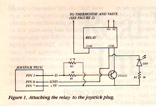
Before we get any further into the circuit, there's something you need to know about the difference between PORTA and PORTB. In the 800 and 400 each of the I/O pins in PORTB has a little "helper" in the form of a + 5 volt source connected through a 4.7K resistor. The PORTA pins don't have this and when you send a "high" through a PORTA pin, it doesn't have nearly enough power to make this circult work.
So I added a "helper" to this circuit for XL/XE owners who have only PORTA available. In Figure 1, resistor R3 is drawn with a dotted line. R3 is a 4.7K resistor that supplies + 5 volts to the output line, similar to what's built into PORTB. You can operate this circuit from PORTB on an 800 or 400 if you omit resistor R3 and make the programming changes I'll specify later.
WATER VALVE
As it comes from the factory, the RainMatic Corp. water valve has a compartment for four C batteries, and an electronic programming module with an LCD display for setting up the watering schedule. I removed the programming module to connect the Atari in its place. I also removed the battery compartment and substituted a longer-life 6 volt lantern battery. This left two sides of the assembly open, so I had to make two crud plastic covers and caulk them well, to keep moisture, dust, and insects out of the valve assembly. The wiring simply comes out through the caulk.
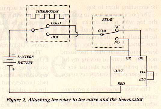
The lead from the negative side of the battery first hits the thermostat, assuring that the valve will stay closed until the air temperature in the greenhouse is high enough. (see figure 2)
The normally closed (NC) pin of the relay is connected to the black wire of the valve coil, which opens the valve. The normally open (NO) relay pin is connected to the green wire of the valve coil, which closes the valve.
Normally the valve is open and the water flows. To turn the water off, my program POKEs a 1 into PORTA and + 5 volts is sent on pin 1. This closes the relay and voltage from the lantern battery is applied through the thermostat and the relay to the green lead on the valve, which closes.
Voltage continues to be applied to the green lead, but nothing happens. There is no battery drain because a switch inside the valve opens the circuit. When it's time for the water to come on again, the program POKEs 0 into PORTA. The relay releases, removing voltage from the green lead and applying it to the black lead. The valve opens and the water flows again.
A lead runs from the COLD side of the thermostat to the green wire of the valve. This insures that the valve will automatically close if the temperature drops below the threshold while the water is on.
PARTS LIST
PC BOARD -- Radio Shack #276-168
R1, R2 -- 1K Ohm Resistors
R3 -- 4.7K Ohm Resistor
TRANSISTOR -- 2N2222
RELAY -- Radio Shack #275-216
LED from Radio Shack
9-conductor ribbon cable
9-pin female connector
THE CLOCK
The heart of my Atari clock is a machine-language program running in the vertical-blank interval. It is based on OS location RTCLOCK(18, 19, 20), but only reads location 20, which counts jiffies (1/60 seconds).
Real-World Interface uses locations 19 and 18 to store the count of seconds and minutes, respectively, obtained by watching the content of location 20, resetting it when it reaches 60, and incrementing the seconds count at the same time.
I wanted to store the count of hours in Page 0 so it could be accessed quickly I chose location 207, which seems to be unused by most versions of DOS and BASIC. I also used 208 and 209 for counting jiffies. Location 20 is actually updated ever~ 1/59.92334 second--not every 1/60 of a second. In the short run, this isn't enough of an error to cause much trouble. But with a continuously run- ning clock, the error builds up sur- prisingly fast.
So I built a correction factor into my clock. Since the Atari timer gains a tiny fraction (0.07666) of a jiffy each second, I calculated how many jiffies it was gaining in a minute (4.5996). Dividing this number into the number of seconds in a minute yielded 13.044612 seconds, which told me how often I needed to increment the jiffy counter to keep the clock as accurate as possible. Since 13.044612 seconds equal 782.67672 jiffies, I rounded off my number to 783. That's what the clock program counts to before adjusting the jiffy counter.
I realize this may seem like nitpicking to some, but achieving the highest possible accuracy allows a continuously running program like my greenhouse tender to go longer between clock resets.
ABOUT THE PROGRAM
Type in Listing 1, INTRFACE.BAS, check it with TYPO II and SAVE a copy before you RUN it.
Some simple line-editing will turn INTRFACE.BAS into a universal relay-controlling program. Since the water goes on when the relay is off, all that's required is to replace the word WATER with RELAY and ON with OFF (and vice versa) in the following lines: 900, 920, 1020-1070, 1112-1160, 1190, 1200, 1280, 1320. Also swap lines 500 and 510.
To RUN the program using PORTB on an Atari 400 or 800, just change line 5 to: 5 LET A800=1
When RUN, INTRFACE.BAS loads my machine language timing routine into the second half of Page 6.
Next, the variables are declared and the clock is initialized beginning at line 100. The program asks if you wish to reset the clock, which is on a 24-hour cycle, not 12 hours, and will accept either an uppercase or lowercase response.
If you choose to set the clock, the time is displayed onscreen until you press [START]. If the clock hasn't been set, don't answer No to the reset prompt, otherwise the clock will run at one-fourth speed. Merely stopping INTRFACE.BAS will not stop the clock.
After configuring the port for output, the program calls subroutines at lines 880 and 1110 that request all timing parameters. These parameters specify how the relay will function. First the program asks for the earliest and latest start times. If you answer the first prompt with a [RETURN] only, it will assume that round-the-clock operation is okay.
Next, the program asks for the length of time you wish the water to be on, and the length of time you wish it to be off. If you press [RETURN] at each of these prompts, the program jumps to the manual operation routine at line 1240. This routine asks if you wish to turn the water on or off before exiting the program.
Before operation actually begins, the time is displayed at the top of the screen. Several options are offered at the bottom of the screen.
At this point you can stop the program with the water on, stop with water off, or if you want to change one of the parameters, you may re-start the program without resetting the clock. These options are also available while the program is running. Finally press any key to start the timer.
PROGRAM TAKE-APART
In lines 440-460, the program checks to see if it's time to operate a relay. If so, lines 500 and 510 initialize variables before calling the timing and relay subroutines.
In lines 600-730, the program gets the correct time, adds to it the amount of time specified for the relay to be operated or released, and adjusts any minute or second values greater than 60, or hour values greater than 24.
Lines 770-820 contain the timing loops, one each for second, minute, and hour.
Lines 840-847 hold the subroutine that displays the time at the top of the screen.
John Little has been programming Ataris and tinkering with hardware projects since 1984.
Listing 1: INTRFACE.BAS Download