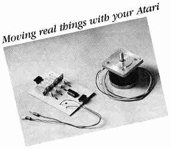
Stepper Motor Robot-Controller
Have you ever wanted to use your Atari to move
things? Perhaps to roll a robot around, direct a photocell scanner from
across a room, or move a manipulator arm? Stepper motors can do it-with
the interface board and software described in this article Note. To complete
this project successfully, you must be enough of an electronics hobbyist
to read schematic diagrams and solder a circuit board. The BASIC program
works on all 8-bit Atari computers of any memory size, with disk or cassette.
(Antic successfully tested the stepper motor interface board and software provided by the authors. But because we wanted to get this important (and thoroughly detailed) material into print as quickly as possible, we did not take time to rebuild the hookup from scratch, as is our usual procedure when publishing hardware-software projects. -ANTIC ED)
HOW STEPPERS WORK
Stepper motors rotate only a little bit when pulsed, typically 1.8
to 3.75 degrees. But they do it with precise accuracy and powerful torque.
These motors move something into position and lock it there firmly. Unlike
most other tools for moving things, stepper motors can tell you exactly
how far and how fast they have moved, and which way they are pointing.
All electric motors have two basic parts-the armature, which turns, and the stator, which doesn't. Magnetism pushes and pulls the armature with the stator. In a conventional motor, when the armature almost gets to where magnetism is moving it, brushes contact new areas and the magnetic polarity is switched. The armature suddenly has a long way to go again-rather like coaxing a horse forward with a carrot on a stick.
Most conventional motors have only one stator coil, but stepper motors usually have four. Steppers also use a permanent armature magnet instead of armature coils, commutators and brushes. Stepper motors let the armature catch the carrot, and they magnetically lock the armature into each position. Turning on another coil of the stator and turning off the previous coil moves the armature another step and locks it into a new position.
The stepper motor controller rapidly distributes precisely timed bursts of electricity to the different coils of the stepper motor and provides the timing to control the speed. It can also count the number of steps traveled-that is, how far the armature has been turned-with computer-like accuracy. And this is where your Atari comes in. The software and hardware explained in this article will let you use your Atari as a stepper motor controller for many robotics-type projects of your own choosing.
HOOKING UP
An Atari 8-bit computer has excellent Input/Output capabilities that
include two joystick ports, each containing four digital I/O pins, two
analog (paddle) inputs, a trigger input, a five-volt direct-current source
(+ 5VDC) and a ground. These items meet the needs of most stepper motors.
The digital I/O lines can be used in a joystick port to turn the stepper
motor coils on and off, while the + 5VDC and ground can power the interface
circuit. The source of the current to power the motor depends on the stepper
motor used.
In our sample interface, we'll use an Airpax 86402, a + 12VDC four-phase stepper. This is a good choice because + 12V is easy to get and the motor is strong and precise-only 1.8 degrees per step-but mostly because it's cheap. In fact, we can buy the whole controller and motor with power supply for less than $25. Steppers are usually fairly expensive, but if you buy from surplus stores the prices get ridiculously low ($3.95 for the one we used).
To turn the stepper motor, we apply + 12V to different phases (combinations) of stator coils in turn. The stepper can be turned in half steps by using another set of combinations. But the half steps don't have the same powerful torque as the full steps and your project will probably not need to use them.
Some stepper motors need different arrangements for coils and phases. These can be obtained from the stepper manufacturer Figure 1 shows which coils to send power to for different amounts of clockwise and counter-clockwise rotation, on an Airpax and similar motors.
We will assign one digital I/O pin in the joystick port to each coil, and use that pinto turn the power on and off for that coil. The Atari software will regulate the combination of coils to power during each phase, take care of the timing and keep track of the stepper position.
We must build a circuit to tell the coils when the joystick lines go high or low. We'll use a 2N3055 transistor to turn the power on and off. A 7404 integrated circuit will turn the transistor on and off with the digital line, and costs as little as 15 cents. A diode keeps the motor noise out of the computer, a pull-down resistor keeps false signals away and a power resistor cools the motor.
SOME SUPPLIERS
Below are three electronics sources where the authors found good deals on key parts for this project. This short list is clearly not meant to be a complete guide to all possible parts suppliers throughout the U.S.
John J. Meshna Jr., Inc.
19 Allerton St. Lynn, MA 01904 (617) 595-2275
Stepper Motor SP-369B31 $3.50
Jerryco
601 Linden Place Evanston, IL 60202 (312) 475-8440
11.5VDC Power Supply J-3895 $7.50
H & M Engineering
1945 5. Lincoln St. Springfield, IL 62704 (217) 787-8422 (after 5 p.m.)
Stepper Motor
Printed Circuit Board $8.50
HIGH-LOW
When the joystick line for a coil goes low, the 7404 sends + 5V to
the base of the transistor, turning that transistor on and allowing the
current from the motor to flow through the transistor to ground, powering
that coil. The current goes through a power resistor before reaching ground,
however, limiting total current flow.
When the joystick line goes high, the 7404 output and the transistor are turned off, stopping the current flow in that coil. We invert the pin/power relationship because the Atari normally puts all four pins high after a system reset. That would simultaneously power all four phases of the stepper before the program takes over and heat up the motor unnecessarily.
A diode between the 7404 and the transistor allows current to flow from the chip to the transistor, but not vice versa. This prevents motor noise from backing up through the system. The pull-down resistor keeps the transistor off until the computer supplies a signal. This is repeated once for each coil. The 7404 handles all four digital signals, triggers each transistor, and is powered and grounded by the joystick port.
The power and ground for the stepper motor come from a + 12VDC power supply. A power supply from an Atari 5200 video cartridge system is rated at + 11.5 VDC, which is close enough. There are ample 5200 power supplies on the surplus market for $7-$8 each.
Assembly of the interface board is comparatively easy, but beginning hardware hobbyists should work carefully and use a low-wattage soldering iron. Follow the schematic diagram in Figure 2 if you are using perforated board, which works fine if you don't want to etch your own board. Or work from Figure 3 if you are making a printed circuit. Use a socket for the 7404, make sure your solder joints are good and don't short the IC 's pins together. Watch out for correct wire connections to the 2N3055.
If you are using the Airpax 86402 stepper motor, connect the two red wires to the positive lead of the power supply. The other four wires are the individual phase wires and should be connected to the board as follows:
Yellow Ql
Orange Q2
Brown Q3
Black Q4
The stepper motor plugs into the interface board via a polarized connector. Plug the power supply to the board, following the correct polarity. Plug the DB9 socket into the first joystic port, plug in the power supply and RUN the software.
Our stepper program was written to control various different motors. And different brands of stepper motor have different maximum stepping speeds. When performing a full-speed movement, the program may sequence the steps a little too quickly for your particular model of stepper motor, which would cause erratic movement. If necessary, insert a FOR/NEXT delay loop between steps, to smooth out the motion.
THE PROGRAM
Type in Listing 1, STEPPER.BAS, check it with TYPO II and SAVE a copy
before you RUN it.
This program was originally written to raise and lower a camera platform in precise increments. (See adjoining story, Steppers In Micro-photography). But the modifications to move almost anything else are simple. The program includes routines for quickly moving the motor in either direction, moving it to a given point, keeping track of the stage position, adjusting speeds, signalling when a move is complete and moving from point to point.
Each time a phase is powered, some I/O pins must be turned on and some off. This corresponds to putting ones and zeros into PORTA (location 54018, $D300). PORTA is the memory location of joystick port 1 when it is being used as a data register. POKE that location with the decimal equivalent of the proper binary number (5 for 0101, 9 for 1001, etc.) to push the four joystick pins high or low. Labeling each phase number with a variable makes it clearer. Then we just POKE PORTA,A:POKE PORTA,B: POKE PORTA,C etc., to turn the motor
By noting how many times we've POKEd the stepper, we can record its motion and then turn it to selected positions with precision. Inserting a FOR/NEXT timing loop creates a variable delay to control the speed. POKE PORTA with A,B,C,D,A,B etc. in order, to turn the motor turns in one direction. If you POKE in the reverse order, it turns in the opposite direction. POKE PORTA with A,E ,B, F,C,G, D,H,A,E,B etc. to turn it in half steps.
PROGRAM TAKE-APART
The program's REM statements explain various sections. Line 310 sets
up joystick port 1 for output. Memory location 54016 ($D302) is the PORTA
control register (PACTL), and these POKEs set up PORTA for output to the
joystick port.
I should mention a few other programming tricks used in the display routines. One trick is to DIMension BL$ in line 270 and PRINT it in line 490 (every time the menu is rewritten). BL$ is a character string filled with blanks, and here it clears the command line.
Second, although the menu and commands are in Graphics 1, the display settings are in Graphics 0. Lines 110-120 print the display and the initial settings. Note that PRINT #6; prints to the Graphics 1 screen, while PRINT is used to print in the text window.
The statistics are updated by POKEs to TXTROW and TXTCOL (memory locations 656 and 657) throughout the program. These locations hold the row and column, respectively, for the current cursor location in the text window. In line 890, for example, each time the program moves the stage and updates P (the present location variable), the cursor goes to row 2, column 28 where P is PRINTed. You must also PRINT a trailing space to clear the old number.
Finally, the ticking noise in the keyboard speaker as the program moves the stage up and down is produced by POKEs to CONSOL, memory location 53279 ($D01F). This is the same location used for reading the console keys. By using FOR/NEXT loops and experimentation, you can create a "fifth voice" for your Atari.
Using stepper motors with your Atari can open a world of computer-controlled precision movement. You can control a robot on wheels powered by stepper motors, using arms controlled by stepper motors, seeing with a scanner positioned by a stepper motor. And who knows what else?
In my own case, I've found that making the robot open the refrigerator door is easy, but how do I get it to take the tops off the bottles?
INTERFACE PARTS LIST
Label   Quan. Description           Radio Shack #  Price
T1-T4     4   TIP 3055 transistor     276-2020     $1.59
D1-D4     4   1N4001 diode            276-1101      $.49
R1-R4     4   1000 ohm 1/2watt        271-1321      $.39
R5-R8     4   50 ohm 2 watt resistor
IC1       1   7404 integrated circuit 276-1802      $.99
              (with 14 pin socket)    276-1999      $.89
S1        1   DB9 socket              276-1538     $2.49
          1   perforated board        276-1394     $1.89
Plus wire, 1 amp fuse and holder, solder, case, printed circuit board if desired, etc.
Scott Kilbourne is the Chief of Medical Photography at Southern Illinois University and president of the Lincolnland Atari Users' Group. Jon Holcomb is a Radiation Safety Technician at the Southern Illinois Unversity School of Medicine. William Hall is Deputy Director of the Illinois Dept. of Children and Family Services. Bill Andrea provided some of the illustrations.
Listing 1: STEPPER.BAS Download