VIEW 3-D
Rotate and zoom 3-D images in ACTION!
by PAUL CHABOT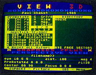
Create 3-D wire-frame outline pictures in your Atari's highest resolutions,
Graphics 8 and Graphics 7+. Magnify shrink rotate, and otherwise shift
your view of the 3-D picture easily and fairly quickly Re-quires ACTION!
cartridge, disk drive and 48K memory Antic disk subscribers can run VIEW3D.EXE
without the ACTION! cartridge. Disable BASIC and use the L option from
DOS 2.0S Disk or cassette.
When Paul submitted View 3-D to Antic, we saw it was easily
the largest ACTION! program any magazine had considered publishing But
in recent months, we have received so many letters from readers wanting
ACTION! that we thought it was time for a monster example of programming
in this powerful Atari language.
Be warned: there are ten separate program listings,
nine of which are dependent on and INCLUDEd into the tenth to form one
main program. Because of the nature of ACTION! there is no TYPO II, so
type patiently and carefully The results will be well worth it. -ANTIC
ED
There are different approaches to 3-D viewing.
You can leave the viewing point ("eye") fixed and rotate the object. Or
you can think of the object as fixed and change the location of the eye.
These are mathematically equivalent, but conceptually quite different to
most people.
Also, should the projection be perspective or orthogonal?
Where should the focus be placed? View 3-D will allow any combination of
these variations and more. To manipulate a 3-D frame quickly, you need
faster number crunching than BASIC provides. The answer is ACTION!, the
cartridge-based programming language from Optimized Systems Software, which
is becoming increasingly popular with serious Atari programmers.
TYPING IT IN
View 3-D is one program, but it has been split into ten files. Listing
10, called VIEW3D, is the main file which INCLUDEs the other nine. If you
look at the beginning of listing 10, you can see the name of the other
files.
Type each file in the order they are INCLUDEd in Listing
10. Each subsequent file shares procedures from previous ones, none may
be compiled or run independently You can partially check your work by compiling
programs accumulatively in the order in which you type them. For example,
GR78M may be compiled alone. After typing in MISC1, create a temporary
third program which INCLUDEs GR78M and MISCl. This third program, when
compiled, will compile the first two, and so on.
VIEW3D is too large to be compiled and run from the ACTION!
editor. When all your files are properly typed in, clear the editor and,
from the monitor, type: C "VIEW3D.ACT". After the compilation is complete,
type [R] and away you go.
THE PROGRAM
The first thing you should see is the menu screen. View 3-D alternates
between two screens-the menu screen and the view screen. The menu
screen has command options and a disk directory. The view screen
shows your 3D drawing. Shortly after the menu appears, the colors will
alter and the program will switch to the view screen and display a simple
3-D object called "Plane" which is similar to Figure 1.
THE COMMANDS
With the exception of [D], any key pressed will take you to the view
screen. One-key commands are acted upon immediately No [RETURN] is needed.
[B] Returns you to the menu at any time.
[G] Switches you between GR. 7 + and GR. 8. GR.
7+ offers four colors (counting the background), changed with the [C] selection
(below).
[C] Alters the GR. 7+ color registers. The message
line at the bottom will indicate the current color number (0-3), its current
hue and luminence values, plus the word Default.
The keys [C], [H], [L] increment
the color, hue, and luminence. This can be used while in GR. 8. But the
effect may be misleading because the GR.7+ registers and the current screen
registers are being altered but not the GR. 8 default values. The [D]
key resets all GR.7+ registers to default values. These values are updated
each time you load a data file. Also, none of your playing will affect
the menu screen colors, since these are maintamed separately. Any other
key terminates this routine.
[M] Magnifies the object. This-is initially set
at 4 and wraps to 1 when incremented past 9. You won't see the effect until
the picture is redrawn by pressing [SPACE].
[V] Changes the view between perspective and orthogonal.
Perspective, which emulates our vision, takes into account the distance
from the eye, whereas orthogonal is used in drafting and engineering.
Figures 2 and 3 show the difference between perspective
and orthogonal projections.
PREROTATE
These selections let you rotate your object about any of the three
X, Y and 7 axes. The message line shows the values of rx (rotate
X), ry (rotate Y), rz (rotate Z), and ri (rotational
increment). Each time the [X], [Y] or [Z] keys are pressed, the object
rotates about the chosen axis in ri increments. The rotations are
about axes that pass through the focus point.
The [I]/[J] keys increment/decrement the
value of ri in degrees. Negative values of ri make rotations
go in the opposite direction.
POINT OF VIEW
The following commands affect your dimensional view of the object.
[3] Fix EYE/dist. The eye coordinates are controlled
by your joystick. Selections [l]-[4] use the same joystick scheme: Left/right
alters the X coordinate, up/down alters the Y, and up/down while holding
the trigger alters the Z. In selection [3], left/right with the trigger
pressed controls the distance. Press [SPACE] to draw your object from this
new eye location.
Remember that the eye coordinates are relative to the
focus point (see [4] below) and only establish the viewing direction in
the orthogonal view. The eye-object distance is important only in the perspective
view. Keep the distance large to avoid distortion.
[4] Change FOCUS. The focus is the point in space
at which the eye is aimed and through which all the rotation axes pass.
It is normally on or near the object being studied and will be mapped to
center screen (cx,cy). Move the flashing dot with your joystick.
More importantly, watch its coordinates. Use [SPACE] to set your choice.
[5] Change CENTER. This alters cx and cy,
shifting the object. These are actual screen coordinates (0,0 is the upper
left). Use [SPACE] to set your choice and see the effect.
[0] Resets the center, eye, focus, magnification,
and prerotation values to defaults used at start-up.
I/O
[D] Lists up to 22 data files in the menu window, assuming they
have ".V3D" extenders. This is also done automatically at start-up and
after each successful save.
[L] Loads a data file from disk. Answer the input
prompt with a filename only. The program supplies the "D:" prefix and a
".V3D" extender. Upon hitting [RETURN] you'll see the full filespec. Press
[L] again to accomplish the load. Any other key will abort the process.
[S] Saves data to a disk file. The process is the
same as the above [L] load.
[P] Outputs to your printer. After pressing [P]
you may choose to print the picture data [D] or the picture [P]. The picture
is produced by a short screen dump for a Gemini l0X. You'll get best results
by printing the GR. 8 picture.
To alter the printout procedure for your own printer,
examine the Prnt procedure in the PRINTIO.ACT file and adapt accordingly.
The st array contains printer control codes 26, 51, 16 which, on
the Gemini, set the line feed to 16/144 inches. In the pre array,
the 27, 75, 192, 0 mean print normal-density graphics (60 dots/inch) using
192 + 256 * 0 characters. If you have an Epson FX-80, for example, you
need only change the line feed commands: Change the 16 to 24 in the st
array, and later in the procedure at st(3)= 16. Also, change the
20 to 30 in st(3)=20
3-D DRAWING
It's not easy to draw in 3 dimensions. The easiest way to learn is
simply to try it. Concentrating on the changing coordinates in the message
line may be easier than watching the dots and lines on the screen.
However, before you start, you may wish to save the object
currently in memory. The process is easier to understand if you use the
EDIT command, [2], to display a blank screen. Each time you press the [SPACE]
bar, the screen will step through the drawing process of the object in
memory, showing you how to construct a drawing.
To get started on your own, press [0] to use default values.
To create a blank screen, press [2] then [1]. The joystick moves a flashing
dot, whose coordinates appear in the bottom line. Position the cursor where
you want it, and establish that point by pressing the [SPACE] bar. Your
current updated point number will be displayed in the bottom line. Next,
move the cursor to your second location, press [P] to switch from "Plot"
to "LineTo" and press [SPACE] to draw the line.
For starters, keep it simple, or try editing a sample
drawing. (The program can take up to 200 data points.) To edit a previous
drawing, press [1] to ADD points and lines. As you step through the drawing
by pressing [SPACE], you can change any of the values at any point, or
you can begin adding to the last points. You can, of course, save your
object to disk at any time.
DATA STORAGE
At this point, you need to understand a little about how data for your
3-D object is stored. The INTeger array P contains all the information
in the following format:
P=[n:xyz:d:x:yz:c:......xyz:c:.....]
P(0)=n is the number of data points in your object.
The next four integers contain EYE data. The first three indicate the direction
away from the FOCUS, and the fourth gives the distance.
The following four integers contain the three space coordinates
of the focus point and a presently unused value. These nine integers are
followed by n data sets for your object. Each is made up of four integers
containing the three space coordinates for a point and a fourth coded message.
The encoding of the fourth integer is given by c = color + 16 * p, where
p=0 for "LineTo" and p=1 for "Plot".
SAMPLE DATA
You can enter the data in figure 4 in the ADD mode to create a house
with windows and a red chimney Press [2], then [1] to clear memory Now
use your joystick to get the coordinates in the message line to match those
of the first point in the example. Hit [C] and [P] as needed and set the
data by hitting [SPACE]. Now do the same for the second point in the example,
etc.
You can even do a little at a time. Just save the portion
you've done. Next time load in this file, press [1] and continue from where
you left off. A couple of examples will show you how to read the notation.
"10 20 15:P2" means to Plot (10,20,15) in color 2. Whereas "20 20 30:L3"
denotes a color 3 LineTo (20,20,30). Each example has suggested EYE and
FOCUS data.
Longtime Antic contributor Paul Chabot is a professor of mathematics and computer science at California State University Los Angeles. He wrote "Splash In ACTION!" in our April 1985 issue.
Listing 1. GR78M.ACT Download / View
Listing 2. MISC1.ACT Download / View
Listing 3. COLORS.ACT Download / View
Listing 4. DRAW3D.ACT Download / View
Listing 5. UPDATES.ACT Download / View
Listing 6. STICK3D.ACT Download / View
Listing 7. DISKIO.ACT Download / View
Listing 8. PRINTIO.ACT Download / View
Listing 9. MENU3D.ACT Download / View
Listing 10. VIEW3D.ACT Download / View
Figure 4 data: HOUSE.V3D Download
VIEW3D.EXE Download