THE PARALLEL BUS REVEALED
100,000 bytes per-second
Part one of a four-part series
by EARL RICEUntil now, the Parallel Bus Interface has been one of the big mysteries of Atari XL computers. This important Antic series-by one of Atari's former top technical executives-will at last provide all the information necessary for tapping the power of this 100,000 byte per second connection.
If you own an Atari 600XL or 800XL, you've
probably noticed a little plastic cover on the back. Above that cover
are the Words "PARALLEL BUS." Until now, this port has only been used for
memory expansion cartridges.
Then last June at the Consumer Electronics Show, the Atari
company finally released full specifications for the Parallel Bus Interface
(PBI). This series of articles is based on that information.
In the next few issues of Antic, we'll explain how the
parallel bus works and how you can use it with your own projects.
IMPORTANCE OF THE PBI
The parallel bus interface runs at the same speed as the 6502 microprocessor-and
it can transfer information more than 40 times faster than the serial connector.
The serial connector can transfer no more than 2400 bytes
per second. The parallel bus can easily transfer 100,000 bytes or
more per second, depending on software execution speed. This speed
allows you to design controllers for hard disks and other high-speed devices.
WHAT THE PBI IS
Basically, the parallel bus connector is an extension of the 6502 data,
address, and control signals. These signals aren't buffered, and
can drive only a very limited electrical load. Unmodified, there
isn't very much you can do with the PBI. When used with appropriate
software and hardware, however, the PBI becomes an extremely powerful extension
of your computer.
Fortunately, the PBI's design is easy to understand.
Additionally, most of the software you'll need is already in the Operating
System. This code, called the Generic Parallel Device Handler, resides
at location 58511 ($E48F), just waiting to talk to your high-speed devices.
All you have to do is write the low-level hardware driver software and
combine it with your hardware.
But first you need to see how the PBI works.
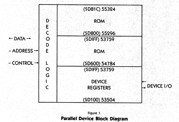
A parallel device (Figure 1) is essentially a circuit board containing five key elements:
- A ROM chip containing both the low-level driver software and a Device Handler Table.
- Any RAM required for on-board buffers.
- Some address-decoding logic.
- A hardware-select register.
- The functional circuitry itself. (Perhaps an I/O device such as a universal asynchronous receiver/ transmitter (UART) to drive a modem, or a parallel interface adapter (PIA) to drive a printer.)
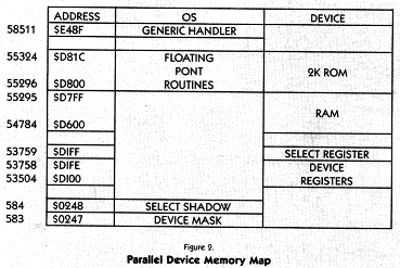
The PBI's ROM space is mapped into the same area as the OS conversion routines from ASCII to Floating Point. The computer's memory management IC switches out the OS ROM when an external device is selected, and switches back in when it's done. The catch is that your external device can't use the floating point software in the OS. it also can't use any function of the OS or application software (like BASIC) that uses floating point routines.
Since most external devices are essentially I/O peripherals, these restrictions should not create many programming problems.
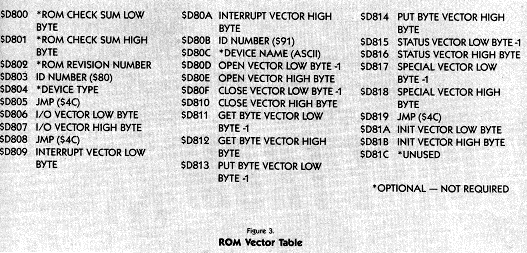
The first 26 bytes of ROM contain a data table (Figure 3). This is a handler table which has the same format as the other OS vector tables. Note that some of the data is optional. The required data consists of ID bytes used by the Generic Handler to validate the presence of a parallel device, and JUMP vectors to device functions.
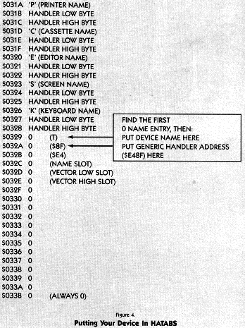
During a coldstart, just before attempting to initialize a cartridge, the OS will poll for parallel devices. If the ID bytes are correct, the OS will execute the JMP to the INIT routine at 55321 ($D819) through 55323 ($D81B). This routine must put the address of the Generic Handler (58511, or $E48F) into the OS handler table (HATABS) along with the device name (T:, for example).
That done, your routine sets its select bit in the Device Mask, performs any device-specific initializations and ends with an RTS instruction.
That's really all it takes to let the OS "talk" to your device. Of course, there are the low-level device drivers to consider, but we'll examine them in a later article. For now, remember that the OS simply needs to know that your device exists (have its bit set in the Device Mask) and to have the Generic Handler's address in HATABS (Figure 4).
The OS can handle up to eight devices on the PBI. The OS selects a device by setting the appropriate bit in the Hardware Select register, located at 53759 ($DIFF). BIT 0 selects DEVICE 0, BIT 1 selects DEVICE 1, and so on.
Just like the other registers in the corn this one has a shadow location. The computer uses shadow registers to update the values in its hardware registers. These values are updated 30 times per second. The Hardware Select register's shadow location is at 583 ($0247).
SELECTING DEVICES
Before selecting a device, the OS looks at the Device Mask (location
583, $0247) to see if such a device really exists. Recall that this
was the bit set by the initialization routine.
Parameters are passed between the OS and the device using
the A, X and Y registers plus the Page Zero I/O Control Block (IOCB).
The carry flag tells the OS whether or not the device
performed its requested function. The device sets the flag when it
has performed its function. Otherwise, the carry flag is left RESET
(0).
The A register passes a data byte, the X register contains
the index to the originating device's IOCB, and the Y register contains
a Device Status byte. This is the same as any other Central I/O (CIO)
operation.
By the way, this is a good place to mention that Atari's
Technical Reference Notes (CO16555 Rev. A) are worth their weight in system
errors. The basic operation of CIO, IOCB'S, Device Status codes and
the like are all presented concisely. If you are serious about writing
professional-level software or designing any kind of hardware for the Atari
computer, this manual is a must. As we go along, I'll briefly explain
the concepts you need for these articles, but these explanations are not
offered as a substitute for the Tech Reference Notes.
SUMMING UP
So far we've learned: The OS contains a Generic Handler for parallel
devices. It selects one of up to eight devices through a hardware
register and keeps track of it through a shadow register. The parallel
device has a ROM containing low-level driver vectors (and, perhaps, the
drivers themselves) and an INIT routine. During coldstart, the OS
will run the INIT routine and the device will declare its existence by
writing its bit into the Device Mask and putting its name, along with the
Generic Handler's address into HATABS. In operation, the device and
the OS communicate through the 6502's A, X, and Y registers plus the Page
Zero IOCB. The parallel device cannot use OS Floating Point routines
because the device's ROM is mapped into those same locations.
Not too hard, huh? Next month we'll look at hardware
requirements, and after that, we'll work up an example and look at interrupts.
In the meantime, try to resist the urge to tear off that little cover.
We'll explain how to do it safely in the next Antic.
Earl Rice held a number of high-level technical positions at Atari,
including head of users group support. His last post there was project
leader of the projected top-of-the-line 1450XL computer.