MAKE A FACE
Parallel printer interface for peanuts
Even inexpensive dot-matrix printers cost several hundred dollars, so I think it's a shame that ATARI owners are expected to shell out a couple hundred more for a parallel printer interface. I recently bought a printer for $290, and was unwilling to pay half again what it cost just so the ATARI could talk to it. Instead, I wrote a routine, which I present here, that allows the computer to communicate with a standard printer through the joystick ports on the front of the machine. By altering the Operating System's "device table", I can even use all of the standard print commands, such as LIST "P' and LPRINT.
To help you get this interface working, I will first discuss some theory, namely: how a parallel interface works, how to send data out the joystick ports, and how to alter the device table. After that, I will describe how to make the cable to the printer, and how to implement the routine. If you're not interested in the theory, skip the first section.
PARALLEL INTERFACING
A parallel interface is one of the several standard ways for a computer to send bytes of data to a peripheral device, such as a printer. In parallel transmission, all of the bits in one byte are sent at the same time along separate wires. First, the computer checks to see if the printer is busy doing something, perhaps printing other characters. It does this by looking at the voltage on the "busy" wire, which is controlled by the printer. If the printer is busy, the computer must wait patiently for it to finish what it's doing before going on to the next step. When the printer is ready, the eight bits of the byte are presented on eight separate wires; a low voltage signifies a bit of 0 and a high voltage of bit of 1. The computer pulses the voltage of another wire to say: "The character is ready, come and get it!" The wire used for this signal is called the "strobe".
This communication between computer and printer ("printer busy" , "printer still busy";"printer ready": "character ready": etc.) is commonly referred to as "hand-shaking, and permits the orderly transfer of data from the computer to the printer.
Now you can see why we need three joystick ports for our parallel interface. Eight wires are necessary for the byte, with additional wires needed for the hand-shaking.
DATA OUT OF THE PORTS
When you use the joystick to play a game on the ATARI, all of the wires in the joystick ports are set for input. When you press the trigger, for example, one of the wires is shorted to ground, giving the computer information that it can use to make something happen. However, you can reconfigure these ports to send data out instead of in. The output signals may be used to control lights, your electric coffee pot or, for the case considered here, your printer.
All we have to do to print a charactsr is wait until the printer is ready, present a byte of information at the ports, and pulse the strobe wire.
To configure PORT A (jacks1 and 2), we first clear bit 2 of the control location PACTL (54018), and then store a byte into PORTA (54016) which specifies the direction of subsequent data flow. Each bit of the byte corresponds to one wire of the port. If this bit is equal to 1, that wire will be set for output; if it is zero, that wire will be used for input. For example, storing a binary 00011001 (decimal 25) in PORTA configures three of the wires for output and five for input. Once this is done, you must set bit 2 of PACTL back to one in preparation for using the port.
After repeating this procedure with PBCTL (54019) for PORT B (jacks 3 and 4), you may print a character using the routine presented below, which waits until the printer is ready to receive a character, presents the character at the ports, and pulses the strobe to tell the printer that the character is available.
ALTER THE DEVICE TABLE
The ATARI Operating System sets aside a group of memory locations to use as a "device table". This table tells the computer where to find the routines for different output devices.
If you were to look in locations 794 (decimal) and following, you would find a series of one letter ID's (e.g. "P" for printer, "C" for cassette, etc....) each followed by a two-byte address. Each address points to another table which contains a set of pointers or "vectors" to different routines for the specific devices (for more detail on this, see page 123 of the Atari Technical Reference Notes). These include routines for opening the device (called when you execute a OPEN #7,8,0,"P:", for example), sending a character to the device, closing the device, etc. If we want to access our own printer code using standard BASIC commands, we need to construct a vector table which points to our printer code and then change the pointer in the ATARI's device table to point to our vector table. It's as if we are telling the device table:
"Look, I have a vector table that points to some routines for printing characters. It's located at memory location 1536. When the Operating System asks you where it should go for the printer vector table, please give it my address." Later, when we execute a printer command, such as LIST "P", the Operating System will go to the device table to ask it about printer routines, and the device table will direct it to our routines. In the case of our printer routines, we set the "OPEN" vector to point to the code that reconfigures the joystick ports, and the "PUTBYTE" vector to the code that sends one character to the printer.
Note, however, that whenever [SYSTEM RESET] is pressed, the Operating System will reinitialize the device table. Thus, whenever this key has been pressed, you must alter the table again so it will point to your own routine.
MAKING THE CABLE
To make the cable, you will need the following hardware:
1. Three female DB-9 plugs. I suggest you use the all-plastic ribbon cable type. You may have to search around for these.
2. About 10 feet of cable. If you use ribbon cable, get it with 25 conductors. Although you won't need all the wires, it will help you to make good strong connections.
3. One Centronics-type, 36-pin male plug. This will plug into the printer.
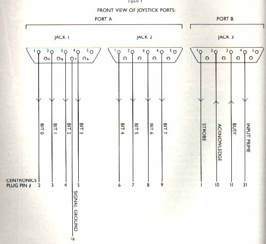
When you've bought these items, you're ready to warm up your soldering iron and put things together. The pin connectors should be made according to the diagram below.
Although the "input prime" and "acknowledge" wires are connected, they are not used by the routines I've presented here. This wiring diagram assumes a standard parallel interface. You should check your printer manual to make sure it isn't different.
If you use ribbon cable to make your cable, you can simply snap the DB-9 plugs onto the cable at the ATARI end, and solder the wires to the Centronics plug at the other end.
IMPLEMENT THE PROGRAM
One way to get the program into your computer is to type in the assembly language program shown in Listing 1, using the ATARI Assembler/Editor cartridge. This way is best if you are familiar with assembly language programming, since it allows you to easily customize the program to suit your particular needs. Once the program has been entered and assembled, you may save it to disk using one of the options discussed in the Assembler/Editor ot DOS manuals.
When the program has been loaded, and you are ready to use it, you must alter the entry in the device table. First, check that location 794($31A contains the ASCII code for the letter P (decimal 80), insuring that locations 795 and 796 hold the pointer to the printer vector table. Next, change this poiter to direct the Operating System to our own vector table which resides at location 1536 ($600). In BASIC, this is done with the statement:
POKE 795,0:POKE 796,6
In the Assembler debug mode, you may use the statement:
C31B< 0,6
When these steps have all been carried out, you are ready to use the standard printer commands to list programs or print data. For example, to list a BASIC program, simply type:
LIST "P"
The second way to implement the printer routines is to type in the BASIC program shown in Listing 2, and run it. Once it has been run, you don't need it around anymore until you press [RESET], and you will be ready to use all of the standard printer commands. For example, the command:
LPRINT "CURRENT VALUE OF X: ";X
may be used to record the value of the variable X on paper.
If you store the BASIC program in the file "D:PRINTSET.BAS", you may set up the printing routines at any time with the command:
RUN "D:PRINTSET.BAS"
SUMMARY
I've presented an inexpensive way to interface your ATARI 400 or 800 computer to a printer using a standard parallel interface. You may wish to add improvements to the program, such as making it invulnerable to [SYSTEM RESET], or storing it as your AUTORUN.SYS program, so that the system will "come up" with the printer routines loaded. Finally, the program demonstrates the flexibility that was built into the ATARI computer which allows it to do things the designers may never have thought of.
Alan Macy, Ph.D., is director of software at DesignWare, a company developing educational computer games for microcomputers.
Listing 1: PRINTER.BAS Download
Listing 2: PRINTER.ASM Download / View