STARTING LINE
Player/Missile Tutorial
Step up your action
by CHRIS CHABRIS
Most ATARI computer owners have heard of Player/Missile graphics. P/M graphics are used in most of the popular machine-language arcade games like Star Raiders, Jawbreaker, and Pac-Man. They are also used in many utility programs such as Atari's Program-Text Editor and Home Filing Manager. Player/Missile graphics capability is built into every ATARI computer, and is unrelated to any language. Players and missiles may be moved around on the screen (which is known as the "playfield") without disturbing the screen display. They are simple to create and animate.P/M graphics are controlled by two of ATARI's custom-designed chips: GTIA and ANTIC. CTIA, the older version of the GTIA chip, is identical for Player/Missile graphics purposes. These chips automatically handle P/M operation while a program is running, so a programmer does not have to write highly-detailed and complex screen-management code. Simple POKE statements in BASIC are all that are needed to control P/M graphics.
In order to understand P/M graphics, we must first define a few simple terms:
1. Playfield Graphics: The playfield consists of all the "normal" graphics; e.g., graphics produced in the various graphics modes using commands like PLOT, DRAWTO, and PRINT. Note that the term "playfield" has nothing to do with whether the program is a game or not. VisiCalc and Shamus both use playfield graphics.
2. Hardware Registers: These may be thought of as special memory addresses on the GTIA and ANTIC chips. Values are POKEd into these registers in the same manner as into normal memory, but each POKE usually has a specific and immediate effect (such as instantly changing the horizontal position of a player or missile).
3. Memory Pages: A page of memory consists of exactly 256 contiguous bytes of memory whose beginning address is evenly divisible by 256. Memory locations 1536 to 1791, for example, comprise Page Six because 1536/256 = 6.
Keeping these fundamental definitions in mind, we will experiment with a single player in this article.
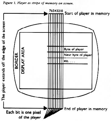 Depending upon the resolution you wish, a player is simply a list of 128 or 256 bytes of RAM. Each byte in the list consists of eight bits, and each bit corresponds to one pixel of the player. To help visualize this, think of a stripe, extending from the top to the bottom of the screen, made up of eight smaller stripes packed tightly together. If the player is 256 bytes long, the stripe consists of 256 horizontal lines, each line of eight small squares representing one byte of eight bits in memory. Figure 1 will help you see this image.
You can "turn on" any combination of the 256 x 8 = 2048 bits that represent the player by setting that bit to equal a "1". You can turn it off by setting that bit equal to "0". To do this, however, you must first give ANTIC information about how to display these bits on the screen. It is best to learn this in a step-by-step process. The process is outlined below and is illustrated with a sample program which displays player 0 in the center of the screen (the four players are numbered 0 through 3).
STEP 1 Select the size of your player.
Choose either single-line or double-line resolution. Single-line resolution gives players the height of a Graphics Mode 8 pixel (high resolution), while double-line corresponds to Graphics Mode 7 pixel size (lower resolution). Then choose the width of the player: "0" for the width of a GR.7 pixel; "1" for double that width; or "3" for quadruple that width. To make the sample program more understandable, we put the width value in a variable and remember the resolution for later use. The first line of the sample program sets the variable "WIDTH" to zero to make each player pixel equal one GR.7 pixel width:
1000 WIDTH= 0
STEP 2 Reserve memory for your player.
The data representing the player images is stored in RAM. You must be certain that the area of memory chosen for this data will not be disturbed by anything else (such as your BASIC program, variables or strings, or playfield graphics). Therefore, you must lower the upper boundary of RAM so that BASIC and the Operating System (OS) will think that there is less RAM than actually is available (the OS or BASIC cannot disturb this part of memory if it is beyond the upper boundary). You set this upper boundary by examining memory location 106, which always contains the number of pages of available memory, and changing it to a lower value. Subtract eight pages of memory for single-line resolution or four pages for double-line resolution. This saves enough memory for the maximum number of players and missiles, though we only use one player in the example program. After subtracting this block of memory from the upper boundary of available RAM, you must POKE the new value for the upper boundary back into memory location 106, as in the second line of the sample program:
1100 A = PEEK(106):A = A-4:POKE 106,A
STEP 3 Set up the playfield Graphics Mode.
Now that you have reserved memory space for your P/M graphics, you can execute the first GRAPHICS statement of the program with confidence that the screen will not interfere with our player. In the sample program, we use BASIC graphics Mode 0 which gives us 24 lines of 40 characters. We also turn off the cursor and clear the screen:1200 GRAPHICS 0:POKE 752,1:PRINT CHR$(125)
STEP 4 Set playfield and player colors.
Choose the background color and any other colors you wish to use. The sample program uses Graphics Mode 0 which allows only three colors (for the characters, the background, and the border). We set the playfield background color to black with a SETCOLOR command. Setting the color of a player is more difficult. Although each player can have its own independent color, the color cannot be set with a SETCOLOR command in BASIC. You must POKE the color value into memory locations 704 through 707 (colors for players 0-3 in that order). The value to POKE to these "color registers" is given by the formula:COLOR = HUE * 16 + LUMINANCE
where HUE ranges from 0 to 15 (the second parameter in the SETCOLOR statement) and luminance from 0 to 14 (even numbers only). Incidentally, instead of using the SETCOLOR command, you could also POKE colors into the playfield registers, addresses 708 through 712. For the sample program we chose HUE 3 (red-orange) and LUMINANCE 6, and the value to POKE is 3*16 + 6 or 54. The next two lines of our sample program set the color for both playfield and player:
1300 SE-RCOLOR 2,0,0
1400 POKE 704,54
STEP 5 Tell GTIA how wide to make your players.
 This may be accomplished with a single POKE to locations 53256 through 53259 for players 0-3. You should become comfortable with the POKE statement, since it is necessary for every P/M operation when writing in BASIC:
1500 POKE 53256,WIDTH
STEP 6 Tell ANTIC where to find your players.
Hardware register 54279, called PMBASE, should be POKEd with the page number of the start of the memory area reserved for P/M graphics. You must multiply that page number by 256 to find the actual starting address in RAM (remember that a page of memory is 256 bytes long). In the sample program we stored the value for PMBASE in the variable A. Now we tell ANTIC where to find the beginning of our reserved memory for P/M graphics:
1600 POKE 54279,A
1700 PMMEM=A*256
STEP 7 Determine the horizontal and vertical positions of your player.
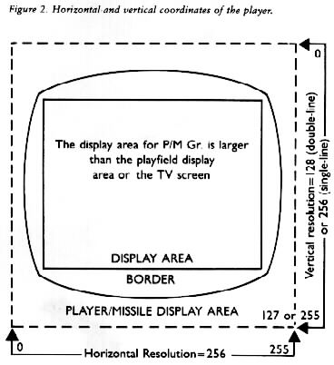
The values for horizontal and vertical positioning of a player are independent of the current Graphics Mode. Horizontal positions may range from 0 to 255. Values of 0 to 46, however, will cause the player to "appear" off the left edge of the screen and it will not be seen. Similarly, values of 209 to 255 will put the player off the right side and it will not be seen. Vertical positions range from 0 to 127 for double-line resolution and from 0 to 255 for single-line resolution (this range is the number of bytes in the list that makes up the player). For singleline resolution, positions 0 to 31 and 224 to 255 are off the top and bottom of the screen. These numbers are halved for double-line resolution. Note that these "off-screen" values will vary slightly depending on the scanning adjustments of your television set or monitor.The vertical position of a player is actually determined by the first byte in the player that is not zero (or blank on the screen). For example, if a player's vertical position were zero and every byte in its list were equal to 255 (all eight bits were "turned on"), the player would appear as a solid stripe of color extending from the top of the screen to the bottom. If the vertical position were eight, bytes 0-79 of the player would be equal to zero (all eight bits "turned off"). Figure 2 explains this. In our sample program, to indicate a position in the approximate center of the screen in double-line resolution, we set the variables P0X to 128 (half of 255) and P0Y to 64 (half of 127) to represent the horizontal and vertical coordinates of Player 0:
1800 P0X = 128:P0Y = 64
STEP 8 Clear memory garbage from your P/M graphics area.
This is accomplished with a FOR-NEXT loop. A zero must De stored in each of the 1024 bytes (four pages, as we determined in step 2) of the reserved P/M graphics area, so:
1900 FOR L = PMMEM TO PMMEM + 1023:POKE L,0: NEXT L
STEP 9 "Draw" your player on graph paper.
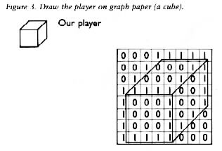 This step requires graph paper. Or you can draw a grid eight pixels wide and as many bytes high as you wish. Remembering that player is eight pixels wide, draw your player by making each bit that you wish to "turn on" equal to a number one. While you might want a long and narrow player, most are no more than 24 pixels high. For our sample program, we draw a player which is a small cube eight pixels high and eight pixels wide (see Figure 3).
STEP 10 Calculate the decimal values for each line in your player.
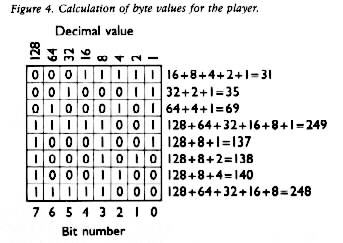
Having drawn your player, write the following numbers above each of the eight (there should be only eight!) columns of pixels of the player, starting from the left: 128,64,32,16,8,4,2,1. These numbers correspond to the binary value of bits seven through zero of a byte of memory. The value of each row or byte of the player is found by adding up the numbers above the columns whose boxes in that row contain a number one. See Figure 4 for an example using our cube.
STEP 11 Place the byte values for your player's shape into a DATA statement.
For the cube example, the DATA statement is:
2000 DATA 31,35,69,249,137,138,140,248
STEP 12 Place this DATA into the memory area for Player 0.
Table 1 lists the locations in the P/M graphics area which are reserved for each player. Find the proper resolution and go down the column until you find the number to add to PMMEM (see step 6) to obtain the starting address for a particular player's list of bytes. Add the vertical position of this player and you have the memory address to begin POKEing in the numbers in step eleve@s DATA statement. In the sample program, a FOR-NEXT loop is used to POKE in this data:
2100 FOR J=PMMEM+512+P0Y TO PMMEM+512+P0Y+7:READ BYTE:POKE J,BYTE:NEXT J
STEP 13 Tell ANTIC the resolution of your players.
 POKE 46 into memory location 559 for double-line resolution or POKE a 62 into the same location for single-line resolution.
2200 POKE 559,46
STEP 14 Tell ANTIC to activate P/M graphics.
Everything is now ready to "enable" Player/Missile graphics on your computer. Do this by POKEing 53277 with the value 3 (always use a 3).
2300 POKE 53277,3
STEP 15 Putting your player's horizontal coordinates into the proper registers.
Without this last step, the players would be turned on but invisible because ANTIC could locate them at horizontal position 0 (off the left edge of the screen, as we saw in step 7). The horizontal position of the player is controlled by POKEing that coordinate into addresses 53248-53251 for players 0-3. The last lines needed in our program are:
2400 POKE 53248,P0X
9999 END
When you have entered all sixteen of these lines into your computer, type RUN and press [RETURN]. After a few seconds, you should see a small orange cube in the approximate center of a black screen, and the "READY" prompt in the upper left-hand corner. If this does not happen, check for typos. You should debug this program and have it working before going on because we will use it to illustrate the principles of P/M movement.
First, add a line to your program that will read a Joystick plugged into Port One:
2500 J = STICK(0)
Consult pages 59-60 of your BASIC Reference Manual to find the values for the STICK function for horizontal and vertical manipulation of the Joystick. They are:
14 for Up, 13 for Down, 11 for Left, and 7 for Right
As we determined in step 15 of the set-up procedure, player zero's initial horizontal position is controlled by POKEing a value into hardware register 53248. In fact, this may be done at any time during the program. Armed with this knowledge, we write the next two lines of the sample program:
2600 IF J = 7 THEN P0X = P0X + 1:POKE 53248,P0X
2700 IF J = 11 THEN P0X = P0X - 1:POKE 53248,P0X
This fairly straightforward code determines if the stick is pushed right or left. Then it increments or decrements the variable POX and POKEs the new value into player zero's horizontal position register (53248).
Vertical motion, however, is not as simple. There are no vertical position registers. To move player zero vertically, we must move the bytes that represent it through the reserved area of memory.
Remembering that each player in double-line resolution requires 128 bytes of the reserved P/M memory, look at Table 1 again. The memory for player zero begins at 512 bytes offset from PMMEM (1024 bytes in single-line resolution). We will use a FOR-NEXT loop to move only the bytes that contain data for that player forward one byte in memory. Since this routine is too large for one line, we use subroutines:
2800 IF J=14 THEN GOSUB 3100
2900 If J=13 THEN GOSUB 3200
3000 GOTO 2500
When the Joystick is pushed up (the STICK function returns a value of 14), we want to move the player towards the top of the screen. This means moving it "backwards" in memory (recall that the 128 bytes for the player start with byte 0 off the top of the screen and end with byte 127 off the bottom). Likewise, we move the bytes "forward" in memory when the stick is pushed down (STICK(0) = 13).
First, the lines of code for the upward movement:
3100 FOR L=0 TO 9
3110 POKE PMMEM + 511 + P0Y + L,PEEK(PMMEM + 512 + P0Y + L)
3120 NEXT L
3130 P0Y = P0Y-1
3140 RETURN
We loop from 0 to 9 because our player is eight bytes long: 0 to 9 allows an extra byte on either side to be moved. If these bytes weren't included, the player would be copied backwards one byte, but the last byte would appear twice - in both the old and new locations. The zero at the end wipes out the old value for the last byte. Line 3110 does the work. There is only a difference of one byte between the address being PEEKed in the second part and the one into which its value is POKED in the first part of the expression. The constant 512 is decremented to 511, so the address being POKEd is one lower than the one being PEEKed (the variables PMMEM, P0Y, and L remain constant throughout the line. When this is done ten times, the player has been moved backwards one byte in memory, resulting in a slight upward motion on the screen. Line 3130 simply decrements the P0Y variable so that the next vertical motion will take the new vertical position into acocunt when it uses the expression in line 3110. Armed with this knowledge, we write the subroutine for downward motion as follows:
3200 FOR L = 9 TO 0 STEP-1
3210 POKE PMMEM + 512 + P0Y + L, PEEK(PMMEM + 511 + P0Y + L)
3220 NEXT L
3230 P0Y = P0Y + 1
3240 RETURN
In line 3200, the loop is reversed using the decremental STEP-1 clause. The 512 and 511 have been transposed in line 3210 so that the value in the lower address is copied to the higher address. Try to visualize how the routine would fail if line 3200 read the same as line 3100. This would cause the first byte, the zero we added, to be copied over the entire player, thus erasing it completely.
If you have a cassette recorder or disk drive, SAVE your program. Now RUN it again, and move the cube around the screen with a joystick plugged into Port One. Since the program does not TRAP errors or set margins for players, moving your player too far to either side will cause an ERROR #3 (VALUE ERROR) because the P0X variable will become greater than 255 or less than 0. Only numbers in the range of 0 to 255 can be POKEd into RAM addresses or registers. If you move the player too far off the screen up or down, your player will cruise through RAM and may temporarily destroy parts of the Operating System, causing your system to "crash". This causes no damage to the computer, but you might have to shut it off and power-up again if the computer "locks up". So be careful.
These are the fundamentals of Player/Missile graphics. Experimentation will further enhance your ability to use this powerful feature of the ATARI computer.
Listing: PMDEMO.BAS Download
1 REM ** PM DEMO ** ANTIC MAGAZINE
1000 WIDTH=0
1100 A=PEEK(106):A=A-4:POKE 106,A
1200 GRAPHICS 0:POKE 752,1:? CHR$(125)
1300 SETCOLOR 2,0,0
1400 POKE 704,54
1500 POKE 53256,WIDTH
1600 POKE 54279,A
1700 PMMEM=A*256
1800 P0X=128:P0Y=64
1900 FOR L=PMMEM TO PMMEM + 1023: POKE L,0:NEXT L
2000 DATA 31,35,69,249,137,138,140,248
2100 FOR L=PMMEM+512+P0Y TO PMMEM+512+P0Y+7:READ BYTE:POKE L,BYTE:NEXT L
2200 POKE 559,46
2300 POKE 53277,3
2400 POKE 53248,P0X
2500 J=STICK(0)
2600 IF J=7 THEN P0X=P0X+1: POKE 53248,P0X
2700 IF J=11 THEN P0X=P0X-1: POKE 53248,P0X
2800 IF J=14 THEN GOSUB 3100
2900 IF J=13 THEN GOSUB 3200
3000 GOTO 2500
3100 FOR L=0 TO 9
3110 POKE PMMEM+511+P0Y+L,PEEK(PMMEM+512 + P0Y + L)
3120 NEXT L
3130 P0Y=P0Y-1
3140 RETURN
3200 FOR L=9 TO 0 STEP -1
3210 POKE PMMEM+512+P0Y+L,PEEK(PMMEM+5ll+P0Y+L)
3220 NEXT L
3230 P0Y=P0Y+L
3240 RETURN
9999 END
Table 1
Offset Values from PMMEM
                Single-Line Resolution    Double-Line Res.
Unused Area*    + 000  -> + 767           + 000  -> + 383
Missiles        + 768  -> + 1023          + 384  -> + 511
Player Zero     + 1024 -> + 1279          + 512  -> + 639
Player Two      + 1280 -> + 1535          + 640  -> + 767
Player Three    + 1536 -> + 1791          + 768  -> + 895
Player Four     + 1792 -> + 2047          + 896  -> + 1023
* This area is not used by P/M graphics, so it may contain anything desired. It will be protected in the same way as the other reserved memory for P/M.
Table 2
Memory Locations for P/M Graphics
| Memory Address | Function | |
|---|---|---|
| 106 | Contains the number of pages of free RAM in the computer. | |
| 704-707 | Color registers for players 0-3. | |
| 53256-53259 | (H) Width registers for players 0-3. | |
| 54279 | (H) Page number of the start of the reserved area of memory. | |
| 559 | POKE with 62 for single- or 46 for double-line resolution. | |
| 53277 | (H) POKE with 3 to activate P/M graphics. | |
| 53248-53251 | (H) Horizontal position registers for players 0-3. | |
| 623 | Controls priorities of players and playfields. |
An "(H)" before a function description indicates that the location is a hardware register.
Christopher Chabris recently graduated from higb school, and works as a Junior Programmer for CSIBM, a computer service company in Yonkers, N.Y. He is a Chess Master candidate, and has represented the U.S. in international matches.