EDUCATION
Color Codes for Resistors
Show me the way to know ohms
By Charles Moore
 Resistors are essential components of most electronic equipment. They
provide a means for controlling the flow of electrons in a circuit, and
may be of varying construction and value. The amount of work performed by
resistors is measured in ohms, and this value is commonly identified by
an internationally-standardized pattern of color-coded bands painted on
each resistor by the manufacturer. The manufacturer also color-codes each
resistor for its expected degree of performance tolerance, measured in plus-or-minus
a given percent of its marked value. Thus, some resistors are more precise
than others.
Resistors are essential components of most electronic equipment. They
provide a means for controlling the flow of electrons in a circuit, and
may be of varying construction and value. The amount of work performed by
resistors is measured in ohms, and this value is commonly identified by
an internationally-standardized pattern of color-coded bands painted on
each resistor by the manufacturer. The manufacturer also color-codes each
resistor for its expected degree of performance tolerance, measured in plus-or-minus
a given percent of its marked value. Thus, some resistors are more precise
than others.
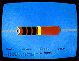
The most commonly seen resistor is a small tubular device containing carbon or other resistive material with wires protruding from each end. Color coding for the values is painted in sequential bands on the tube. The program presented here provides a graphic color display of the standard resistor codes and automatically computes the value in ohms. The program can be used as both a real-time tool to identify resistor values and as a learning aid.
In planning this program, the number of colors in each band representing the value (in ohms) for an average resistor was of primary consideration (see Table 1). As the world-standard identifying scheme requires the use of 12 possible colors in various combinations, the number of playfield colors available in any graphics mode was not enough. Since, however, the average resistor uses only four bands of color, it seemed only natural to use the Player/Missile capabilities of the ATARI, and leave the normal playfield colors free for text and graphics use. This technique allowed display of four P/M colors in addition to the four colors normally available in the Graphics Mode 5, and provided a total display of eight colors on the screen at one time in any combination. The colors used in the program below (Listing 1) are correct for the color setting of my television. However, with the shading required for the colors of a resistor and the difference in color on most TV's, these colors may well be different on your own television. The subroutine provided in Listing 2 will enable you to adjust the colors for proper use of the main program.
PROGRAM DESCRIPTION
I have liberally added REMarks to the program listing to clarify program operation. Even with the REMarks, the program takes up only about 5K of memory (or 4K without remarks), so ATARI 400 and 800 owners alike can use it.
Once set up, the program is simple in operation. Pressing a key causes the key pressed to be tested for a 1, 2, 3, or 4, each of which represents a resistor band. The ON . . .GOTO statement increments a counter (BAND1, BAND2, etc.) for the particular band. Once incremented, each of the band counters is tested for its maximum value. If the maximum value is exceeded, the counter for the first three bands will be reset to zero and the last band counter to ten.
In the first line of the text window a display of what each band color should be is printed in English. To print this, I filled a string (CC$) with all the possible color names in their order of precedence, evenly spaced every nine characters. Then, using the value of the color times nine, I pull out the particular color name needed and place it into the display string for printing. For example, the value for the color orange is three; therefore 3 * 9 + 1 offsets the difference in string length and allows the word "ORANGE" to be printed by accessing the string at CC$(3t9 + 1,349 + 9).
The first two bands are resistor value counters, so I multiply the first band color value by ten and add the second band color value. Then, if the color value of band three is less than ten, I multiply by ten raised to the power of the value of band three. If the value of band three is ten or eleven then I multiply by 0.1 or 0.01 respectively. With this value computed, it is only necessary to adjust for the unit of measure required for display. If the value is greater than 1,000 it is expressed as "K ohms". If it is greater than 1,000,000 it is expressed in "Meg ohms". For simplicity, I allowed for only the two most common tolerance values: 5% and 10% which are represented by the gold and silver colors in band four.
ADJUSTING THE COLORS
Type in Listing 1 and SAVE it to tape or disk. In Listing 1, Line 1340 contains DATA values that determine the colors available for the bands ( see Table 1). You may want to change these values so the actual color you see on your screen resembles more closely the color of the resistors. This color editing is done with Listing 2. After you type in Listing 2, LIST it to tape or disk so you can use it again if you want to.
Listing 1 and Listing 2 are used together. After Listing 2 has been LISTed, LOAD Listing 1 and ENTER Listing 2. This will merge the two programs.
Whenever you adjust the colors you must change Listing 1 as follows:
Insert Line 505 as
505 GOTO 5000
and change Line 910 to
910 GOTO 505
When you are through with the color adjustment, delete Line 505 and restore Line 910 to
9I0 GOTO 510
Do this before you SAVE the adjusted program.
The subroutine takes over the first band and allows you to adjust this band's color using the joystick in Port One. A color value (number) will appear in the text window corresponding to the current value of the P/M color register. Move the joystick up or down to cycle through the changes slowly, or left/right to cycle swiftly. When the band color is correct to your eye, write down the number in the text window. You can then substitute this value for my value in Line 1340.
LINE BY LINE PROGRAM DESCRIPTION
LINE: DESCRIPTION
40 : Dimensions: an array to hold the current band values, a string to
hold the current band color names, and a string to hold all the color names.
70 : will read the band color values into the array.
90 : sets the initial band colors.
110 : opens the keyboard for input.
130-160 : puts labels to the player color-register locations
200-210 : disable the cursor and sets the graphics mode.
240 : puts labels to the P/M location and top of RAM register.
260 : moves the top of RAM down 16 pages and establishes the beginning address
of the P/M area. This moves it below the screen memory making sure the two
do not overlap.
280 : sets P/M to the two line resolution mode.
300 : sets all players to have priority over the play field.
320 : clears the P/M area by setting each byte to zero.
340 : sets the players size to normal
370-430 : will read values for what the players look like and POKEs them
into the P/M area of each player.
450-480 : places the players over the picture of the resistor.
520 : waits till a key is pressed.
540 : tests the key press for a 1, 2, 3, or 4. If not it rings the buzzer
and waits for another key press.
550 : subtracts from the ASCII value of the key press to give a band number.
560-610 : increments the proper band selected.
660-710 : prints the band color names on the first line of text window.
750-850 : prints the ohms value to the text window.
860-880 : prints the tolerance value to the text window.
930-970 : checks the maximum value of each band.1020-1060: POKEs the band
color values to the appropriate P/M color register.
1080-1110: sets the display colors.
1120-1150: draws the body of the resistor.
1160-1190: draws the end of the resistor.
1200-1240: draws the leads of the resistor.
1280 : clears the string that holds the color names.
1290 : reads the color names into CC$.
| COLOR NAME | BAND VALUE |
P/M COLOR |
YOUR COLOR VALUE |
| BLACK BROWN RED ORANGE YELLOW GREEN BLUE BIOLET GRAY WHITE GOLD SILVER |
0 |
0 |
________ |
Listing 1: RESISTOR.BAS Download
Listing 2: RESIST2.LST Download / View