Talk is Cheap
by Ed StuartFor about fifteen dollars you can make your ATARI computer speak. In fact you can make it whistle, hum, sing or curse. You can save the speech on a disk for posterity and play it back anytime you like.
 Sound too good to be true? Well, there are some limitations to this technique, but for the most part it works very well. I've been playing around with it for some time and decided to share it with other ATARI fans.
I am no hardware expert, but I had been looking for an Analog/Digital device for the ATARI and discovered that the ATARI has a built-in A/D converter. In fact it has eight of them--the ports for the paddle controllers. This led me to an article in BYTE (April, '80) titled "Apple Audio Processing" by Mark Cross. This article described a circuit to input audio data to the four game-paddle inputs on the Apple. These are similar to the ATARI paddle ports. Both are A/D converters which generate a count in response to circuit resistance.
The ATARI paddle ports are actually potentiometers (variable resistors) whose resistance changes as the paddle is rotated. If this resistance is changed fast enough, and if it has a direct relationship to the sound waves produced by speech, then we can read the "paddle" values and store the numbers related to the input speech patterns.
A simple circuit converts the voltage produced by a microphone into a variable resistance which is read by the computer. This number is then saved and sent to the TV speaker to produce a voltage which is in direct proportion to the paddle resistance. The result is recognizable reproduction of whatever sounds are uttered through the microphone.
ATARI HARDWARE
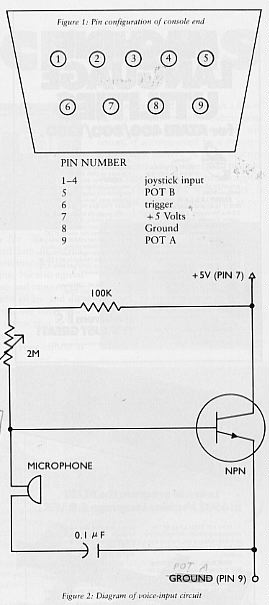
A 9-pin female connector is needed to plug into the joystick/paddle port. APX-9001 is a good plug and it sells for $6.25. The software presented here requires this plug to go into the third port from the left. A description of the controller port pins can be found in section III of the ATARI Hardware Manual. For a brief description of the console end (male) see Figure 1.A double-stranded, insulated wire about two to three feet long should be soldered to your female plug with one wire to pin 9 and the other to pin 7 ( + 5V). The other end of the double wire will enter into the circuit pictured in Figure 2.
The POKEY chip converts the POT resistances into numbers. This technique is called voltage-to frequency conversion, and is noted for low cost and relative inaccuracy, reflected in the speaker output as noise and hiss. Still, most of the original sound remains intact. POKEY normally requires 228 TV scan lines to read the POT. The number produced by POKE is actually a count of scan lines it took to charge a capacitor located in POKEY.
If there is little resistance (paddle knob turned right), the capacitor charges in fewer scan lines and the resultant number is smaller. A fast POT-scan mode is available, which causes the capacitors to charge up in only two scan lines. This fast POT-scan is what we use to read the values from the microphone, because the values must be read thousands of times per second and the normal POT-scan mode is much too slow.
OTHER HARDWARE
The following items are needed to construct the circuit in Figure 2:
1 moving coil type microphone found in cassette recorders
1 0.1 uF nonpolarized capacitor
1 NPN transistor 2N2222
1 2M Ohm potentiometer
1 100K fixed resistor
The small AC current generated through the microphone causes the base current to change through the transistor. This in turn changes the effective resistance of the paddles. The potentiometer is used to "tune" the circuit during program execution. After building this circuit and connecting it to the female port connector, you are ready to talk to your computer.
VERTICAL BLANK AND DMA
Every 60th of a second, whatever program that is executing in your ATARI computer is interrupted by the Operating System to perform housekeeping functions. Converting data through the microphone requires that this interruption not occur. If the vertical-blank process were not disabled, the speech would be unacceptably choppy. The ANTIC chip is continuously fetching screen data from RAM and displaying it on the TV screen. This process is called DMA. DMA also is not acceptable during operation of speech because it slows down the CPU considerably. There is also a period of time when the DMA does not occur (during vertical blank) and this also would cause an unpredictably choppy sound. The sample program turns off both DMA and vertical blank exits during sound input / output process.
EXECUTING THE PROGRAM
The sample program will display the following menu:
1 TALK A BIT
2 PLAY BACK THE BIT
3 TALK A LOT
4 PRINT SUMMARY
5 PRINT THE NUMBERS
6 SAVE THE TALK
7 RESTORE THE TALK
After entering the menu number the program will ask:
WHAT SAMPLE SPEED?
Speed can be from 1-255 and higher numbers cause slower sampling and slower playback.
1 TALK A BIT
After entering the sample speed, press [START]. The screen will black out and you will have about seven seconds of speech. Adjust the potentiometer to get the best quality speech at this point. With a speed of 1, the sampling rate is about 4500 samples per second. Increasing the sample speed number will increase the speech duration but will also decrease the quality of the produced sound. The RAM buffer for the speech is 16K bytes and resides from 16K-32K in your machine. Therefore, you must have at least 40K RAM to run this program with no alterations.
2 PLAY BACK THE BIT
This will play back whatever is in the RAM buffer. Playing back with a sample speed of 1 is at least ten times faster than Chip and Dale.
3 TALK A LOT
This is the same as Talk A Bit, except that you can talk indefinitely and have the speech heard through the TV speaker. Press [RESET] to get out of this.
4 PRINT SUMMARY
Will cause a count of each of the numbers found in the 16K buffer to be printed.
5 PRINT THE NUMBERS
Will print all 16K worth of digitized speech.
6 SAVE A TALK
Will cause the 16K buffer to be saved to the specified file.
7 RESTORE A TALK
Will cause a saved 16K buffer to be restored to RAM. You can then use MENU item 2 to play back the restored speech.
COMPRESSION
The number coming from the POT controller is eight bits and the number sent to the TV speaker is four bits. This program has therefore packed two input voltages into a single byte in the RAM buffer. Other compression techniques such as compression of like characters and Hamming Codes would have to be implemented if this method of generating speech were to be fully implemented.
ATARI D/A CONVERTER
The ATARI computer has built into it a four-bit D/A converter for each of the four audio-output voices. By setting the proper switch this program has used audio channel number one in this mode.This in no way affects what is happening in the other three voices. Setting address $D201 to a $1X causes X to be output to the TV speaker as voltage. X can be a number from zero to fifteen. Each different X sent to this address causes the TV speaker cone to be moved in or out. If these X's are sent fast enough to $D201 then the speaker cone moves very fast and we have sound at frequencies we can hear. This is exactly what our program does with its digitized input.
CONCLUSION
This technique is quite inexpensive and gives one a taste of the machine, its capabilities and limitations. It is fairly easy to implement and the results are reasonably satisfactory. However, if excellent speech is desired it is necessary to obtain a high-quality A/D converter for accurate digitization. To the best of my knowledge there is no commercially available A/D for the ATARI computer yet. When this item becomes available you will have a head start with the experience you may have gained using the technique outlined here, and you may more thoroughly understand the workings of your ATARI computer.
Listing1:TALK.ASM Download / View
Listing2:TALK.BAS Download