THE FDC
LEARN THE SECRETS OF YOUR FLOPPY
by David Small
David Small, creator of the MacCartridge, and Atari hacker supreme, waxes eloquent on the subject of ST floppies and the Floppy Disk Controller. This is a thorough, technical exploration of the subject, but even beginners will gain some knowledge. To get the full benefit of this article, a familiarity with hardware, hexadecimal, and assembly language is helpful. On your START disk, inside the TRAKREAD.STQ folder, is an assembly-language disk reader which demonstrates programming techniques for the Floppy Disk Controller.
 Let's jump right in.
Diskettes are magnetic storage media. In other words, computer bits are stored as magnetic fields on the disk. The actual diskette surface is just iron goo that can be spot magnetized, very much like cassette tape. Unlike cassette tape, which stores music as a varying-intensity magnetic field (analog), the diskette only has two types of magnetic fields which correspond to either a zero bit or a one bit (digital).
The data on the disk is a series of magnetic fields lined up end-to-end. Imagine about 48,000 bar magnets, each with north and south poles lined up end-to-end around a track and you'll have a fair idea of what the fields look like on a disk. Because some of these magnets are pointed in one direction and some in another, the combination of poles-N/N, S/S, N/S, S/N-creates varying magnetic fields. As the drive head passes over the disk, the head senses these magnetic field transitions, or changes, and that is how the data is recorded and reread.
A 31/2-inch ST diskette consists of 80 tracks. Each track is one circular path around the diskette at a certain radius, and at 135 tracks-per-inch, those tracks are very closely spaced! The outermost track is number zero and the innermost track is number 79.
There is a head in the disk read/write mechanism that moves in and out along the tracks. Once the head is settled on a given track, the disk spins underneath but the head does not move. To read a certain place on the disk, the head moves to the correct track (radius), and waits for the data to spin under the head.
It takes three milliseconds to move the head one track. This is called stepping the head, and is done by the stepper motor. When it gets to the destination track, it takes 30 milliseconds for the head to quit rattling enough to do something useful. This is known as head settling time.
Each track is about 6,000 bytes "long". I say long because, although they are on a circular surface, the tracks do have a beginning and an end marked by an index pulse. Every time the disk spins, the drive briefly recognizes one point on the disk which generates a pulse once per rotation. (On 5 1/4-inch disks, a small hole toward the center of the disk is uncovered and a light generates the signal. This same thing is accomplished mechanically on 3 1/2-inch disks by a rectangular hole in the metal hub of the disk.) The disk rotates at 300 RPM (plus or minus one percent), hence there are five index pulses per second, each of which marks the beginning and end of a track.
Typically the track is divided into sectors, which are logical-sized chunks of track. This way you can work with one chunk (sector) of the track instead of modifying the whole thing at once. The Atari ST has nine 512-byte sectors per track, numbered one through nine. Remember tracks are numbered starting at zero; sectors begin at one.
On most computers, a chip called a Floppy Disk Controller (FDC), which sits between the Central Processing Unit and the floppy disk, governs the floppy drive. Think of the FDC as a slow, sophisticated, slow, helpful, slow, and advanced slow chip. If you are programming the FDC, always bear in mind the slow part and you'll save yourself a great deal of trouble.
|
6: DRIVE SELECT B. (Not used on ST). 10: DRIVE SELECT A- NOT. (+0 volts=turn drive & light on. Note this doesn't turn on the motor; see pin 16.) 12: DRIVE SELECT B-NOT. (Not used on the ST). 14: DRIVE SELECT C- NOT. (Not used on the ST). 16: MOTORON-NOT. (+0 volts=start spinning the diskette). 18: STEP DIRECTION. When you step the heod, this line must tell the drive whether to step in or out. See wire 20. 20: STEP-NOT. This line is BRIEFLY brought to +0 volts to step the drive one track in the direction STEP DIRECTION specifies (in or out). 22: WRITE-DATA-NOT. This is actual bit stream headed for the disk track at around 100,000 baud. 24: READ/WRITE-NOT. When +5, the drive is reading. When +0, the drive is writing. 32: SIDE SELECT-NOT. Pull to +0 volts to write to back side of diskette. DRIVE TO FDC:
26: TRACK 0-NOT. +5 unless drive is at track 0, when this pin goes to +0 volts. This is how the drive tells the FDC to quit stepping it towards track 0. 28: WRITE PROTECT-NOT. +0 volts if the write protect tab is set on the diskette; +5 volts if it is okay to write to the diskette. Note: the drive mechanism will prevent writing if this is set even if the FDC tries. 30: READ-DATA-NOT: The actual real live bitstream from the diskette, at 100,000 baud, complete with wow and flutter (the factory options). |
THE CONNECTIONS
To understand the FDC, you must understand exactly what it does to the disk drive. The FDC Track 00 bit, for example, is not going to make much sense unless you've read about the Track 00 detect wire. Since you're using the FDC to talk to hardware, it helps to know the hardware.
The FDC chip used by Atari is the Western Digital 1772. The 1772 is connected to the floppy disk drive with a 14-pin cable. This 14-pin cable expands to a 34-pin ribbon cable inside the drive case. The 34-pin connector has long been an industry standard in 51/4-inch disk drives. Even IBM uses something very close to it, differing only in two wires. Hence, the signals are pretty well standardized. (This is why you can hook a 51/4-inch drive to the Atari ST. See my article in Antic's ST Resource, Nov. 85, titled "ST Uses IBM Disk Files.") Typically the 34 pins are brought out in a ribbon cable, then to an edge connector.
Fortunately, we don't have 34 separate signals to worry about. Every other wire is either Ground or + 0 volts, which helps suppress some of the radio noise the cable puts out. There are only 17 active wires, and the wires are in two groups: FDC talking to disk, or disk talking to FDC. No single wire is bi-directional (see Figure 1).
The voltages on the wires are always either +5 volts (logic one) or +0 volts (logic zero). Generally, when there is some sort of logical function, the voltages work the opposite of what you would expect: +5 volts means "don't do anything;" +0 volts means "begin." The reasons for this are lost in antiquity.
When you see a wire labelled XXX-NOT, it means that when the wire hits
±0 volts (NOT), something happens. This is as opposed to doing something
at +5 volts, which is more standard inside computers. Example: When the
MOTORON-NOT line is at ±5 volts, nothing happens, but when it is
at +0 volts, the motor spins.
| TRACK LAYOUT | |||
| Index Pulse (beginning of track) | |||
| number of bytes |
data (hex) |
||
| Appears once per track for indexing. |
80 | 4E | Data separator synchronization only |
| 12 | 00 | Data separator sync alas | |
| 03 | F6 | "FDC, lock up with me to start." | |
| 01 | FC | Index Mark | |
| 50 | 4E | More data separator sync bytes | |
| Repeated nine times per track producing nine sectors. |
12 | 00 | Help the data sepatator... |
| 03 | F5 | More sync... | |
| 01 | FE | "IAM A SECTOR HEADER" | |
| 01 | Track # | The track this had better be | |
| 01 | Side # | The side number this is (0 or 1) | |
| 01 | Sector # | The sector number | |
| 01 | 02 | Sector size: 02=512. (00=128, 01=256, 02=512, 03=1024) | |
| 02 | CRC | The sector Header CRC | |
| 22 | 4E | Resync Data Separator | |
| 12 | 00 | Resync Data Separator | |
| 03 | F5 | Resync Data Separator | |
| 01 | FB | "I AM THE SECTORS DATA FIELD" | |
| 512 | Data | The actual data bytes (gee whiz!) | |
| 02 | CRC | The CRC of the data | |
| 54 | 4E | Resync data separator | |
| Note that the last 54 4E's become the first 4E's of the next sector, immediately preceding the twelve 00's. | |||
SECTOR THEORY
Having discussed diskette theory and the basic electrical connections, let's talk about sector theory.
The FDC must handle the extremely fast data streams to and from the diskette. Once the disk is formatted-all in one long write operation-any disk I/O is done at the sector level in short bursts. If you are to become an FDC Wizard (and you will), it will be your job to properly program the FDC so it can handle those bursts.
Sectors are read or written, one sector at a time, in discrete chunks. In other words, there is no way to read or write only one part of a sector. The sector is the smallest "addressable" chunk on a disk.
Why 512 bytes per sector (BPS)? Other convenient sizes are 128 BPS (as in the Atari 810 and 1050), 256 BPS (as in many aftermarket 8-bit drives), and 1024 BPS. Atari settled on 512 for the ST because IBM did it that way, and Atari wanted the ST drives to be disk compatible with the new IBM laptops. (And they are.)
When the diskette first comes from the factory, it contains nothing but random magnetic noise. To use it, you must first lay down some marks that are never changed. These mark the beginning and end of each 512-byte sector, and are called address marks. This happens each time you format a disk. Think of it as drawing ruler lines on a blank piece of paper.
Address marks consist primarily of sector headers, which are followed by data fields. There is one sector header and one data field per sector, and nine of them per track, numbered one through nine. Every sector has a six-byte header which identifies the sector number (one through nine) that will immediately follow it. The first four bytes of the header are:
        Western
        Digital       NEC
Byte   Name (ST)   Name (IBM)
 1       Track      Cylinder
        number       number
 2       Side         Head
        number       number
 3      Sector       Record
        number       number
 4      Sector       Number
         Size
As the above table demonstrates, manufacturer terminology is often inconsistent.
You'll find "Sector not found" errors and "Record not found" errors. No
matter, they're the same thing.
The last two bytes of the sector header are known as a CRC (Cyclic Redundancy Check). There are actually two CRC's per sector. This first one-the header CRC-is a special summation of the previous four bytes of the header. The header CRC is calculated only once, at format time, and written to the disk. Anytime the header is reread, the CRC is checked by the FDC on the fly and compared to what is on the disk header. Any difference means that data on the disk changed without the FDC's help. This translates into a disk error.
After the sector header are 512 bytes of data (the data field) followed by a second CRC that checks the preceding 512 bytes of data field. The data CRC is recalculated and rewritten everytime the FDC writes the sector data.
Although the data field is rewritten many times, the sector header is only written once at formatting time. The PDC handles the timing of these operations.
THE GUTS OF A TRACK
What does a track look like at the byte level? A quick way to find out is dump the entire track to memory, using the FDC Read Track command. Alas, there's a catch. Some of the bytes written to a track at format time can never be reread because they are intercepted by the data separator and never seen by the FDC.
Check out Figure 2 for the layout of a track. At the end of the track, there is actually room for one more 512-byte sector, which would give you 80 tracks times 512 bytes, or 40K more storage per disk side. The ST can access this "extra sector," but since the name of the game is IBM compatibility, nine sectors per track is standard.
So, if we dump a track using the FDC's Read Track command, we will not see the clean, well-mannered listing in Figure 2 because those $4E's will be in use by the data separator as it quickly tries to stay in step with the disk. Data won't wait. As the data separator drifts, you will get trash (weird-looking bytes) in the Read Track data. Commonly, the data separator will accidentally lock onto the data bits instead of the clock bits, and the FDC will see lots of $FF's. That's okay, by the end of the $4E field, the data separator should have adjusted itself back into sync. But be forewarned: the data will not appear cleanly and will vary even from read to read.
The bytes in Figure 2 that begin with "F" do not appear on disk the way they appear in the figure because, when formatting the track, the FDC translates these bytes into missing clock pulses that tell the FDC this byte has a special function-be it a sector header, start of data mark, index mark, CRC, or whatever. You won't see these on a track dump because the FDC will be busy.
OPERATING THE FDC
Programming the FDC involves setting up the TRACK, DATA, and SECTOR registers of the FDC, then writing to the COMMAND register Just doing the write will cause the command to execute. You then wait for the FDC to tell you it is finished by watching the IRQ (Interrupt ReQuest) line via the MFP (MultiFunction Peripheral controller) chip, bit five.
Some miscellaneous considerations: You must select the disk-drive number and disk side (done with the Yamaha sound chip, port A, lowest three bits), and you must deal with the DMA controller. But basically, it's a matter of getting the drive online, then writing to the COMMAND register of the FDC to get it to do something.
The TRACK register is used a great deal (Step commands and Sector commands), the SECTOR register is only used for sector I/O, and the DATA register is only used for Step commands because, during sector I/O, the DMA chip handles the data transfer.
THE DREADED MOTORON KLUDGE
Look again at the pinout listing in Figure 1, and you will see that one of the wires going from the FDC to the disk drive is MOTORON-NOT When this line is brought to zero, the motor spins.
There are several subtle considerations here:
-
MOTORON is separate and distinct from DRIVE SELECT. You can select a drive,
have its light on, and not have it spinning; or you can have it spinning
but not selected. Just because they have always worked together doesn't
mean they have to.
-
You must give the motor time to bring the drive up to speed before you
do any reading or writing. The data separator is painstakingly tuned to
data coming in at 300 RPM. Vary that, and the separation will fall apart.
Generally, you need at least 1/5 of a second to get the motor up to speed.
- You need to shut the motor off when you're done so the drive isn't spinning all the time. Otherwise, the head will literally wear a groove through your diskette. On the other hand, if you have a string of read/write operations, you don't want to shut the motor off after each one or you'll have to wait for the motor to get back up to speed before doing any new operation. Normally, Western Digital chips require external hardware to accomplish the above feats. To process a command you switch on the drive motor and wait for it to get up to speed. When done, the hardware keeps the drive spinning another couple of seconds, then reluctantly shuts it off.
up a flag, called
"flock;" which may
be found at $43E in
Scenic TOS.
Western Digital, in their infinite wisdom, gave us some hardware inside the 1772 that helps with this task. If you set the Motor-On flag (see FDC COMMANDS, below), the FDC will turn on the drive, then wait for several index pulses before continuing; since each pulse takes at least 200 milliseconds the drive ought to be up to speed. When the command is done, if ten index pulses go by, the FDC shuts off the motor.
The problem is this: You must have a selected disk out there before the FDC can see index pulses. Therefore, you must leave the drive selected after completing a command or the FDC won't he able to shut off the motor But after the motor shuts off, courtesy of the FDC, the drive still stays on. And that's bad news.
Atari solved this dilemma by looking at the drive each vertical blank (VBL), which is 50 times per second in color and 70 times per second in monochrome. If the FDC has just shut the motor off, the VBL task shuts off the DRIVE SELECT, turning off both the drive and its light.
Ah, but to sample the FDC, the VBL task has to talk to the FDC, which involves talking to the DMA chip first. All this boils down to big trouble if you're in the process of talking to the disk. So Atari set up a flag, called "flock," which may be found at S43E in scenic TOS. Flock must be set anytime you're going to use the FDC. It tells the VBL task- which will certainly interrupt your program a lot-not to touch the FDC for a while. After you are done with the FDC, turn flock off, and the VBL will shut off your disk drive for you.
If you forget about flock, you're doomed in two ways: The FDC will be
stolen from you periodically, or the drive will forget to shut off. Neither
alternative is good.
FIGURE 4
| COMMAMD SUMMARY | ||||||||
| BITS | ||||||||
| TYPE COMMAND | 7 | 6 | 5 | 4 | 3 | 2 | 1 | 0 |
| I Restore | 0 | 0 | 0 | 0 | h | V | r1 | r0 |
| I Seek | 0 | 0 | 0 | 1 | h | V | r1 | r0 |
| I Step | 0 | 0 | 1 | u | h | V | r1 | r0 |
| I Step-in | 0 | 1 | 0 | u | h | V | r1 | r0 |
| I Step-out | 0 | 1 | 1 | u | h | V | r | r0 |
| II Read Sector | 1 | 0 | 0 | m | h | E | 0 | 0 |
| II Write Sector | 1 | 0 | 1 | m | h | E | P | a0 |
| III Read Address | 1 | 1 | 0 | 0 | h | E | 0 | 0 |
| III Read Track | 1 | 1 | 1 | 0 | h | E | 0 | 0 |
| III Write Track | 1 | 1 | 1 | 1 | h | E | P | 0 |
| IV Force Interrupt | 1 | 1 | 0 | 1 | I3 | I2 | I1 | I0 |
| FLAG SUMMARY | |
| TYPE I COMMANDS | a0 = Data Address Mark (Bit 0) |
| h = Motor On Flag (Bit 3) | a0 = 0, Write Normal Data Mark |
| h = 0, Enable Spin-Up Sequence | a0 = 1, Write Deleted Mark |
| h = 1, Disable Spin-Up Sequence | E = 15ms Settling Delay (Bit 2) |
| V = Verify Flag (Bit 2) | E = 0, No Delay |
| V = 0, No Verify | E = 1, Add 15ms Delay |
| V = 1, Verify on Destination Track | P = Write Precompensation (Bit 1) |
| r1, r0 = Stepping Rate (Bits 1,0) | P = 0, Enable Write Precomp |
| r1 r0 WD1772-02 | P = 1, Disable Write Precomp |
| 0 0 6 ms | |
| 0 1 12 ms | TYPE IV COMMANDS |
| 1 0 2 ms | I3-I0 Interrupt Condition (Bits 3-0) |
| 1 1 3 ms | I0 = 1, Not Used |
| u = Update Flag (Bit 4) | I1 = 1, Not Used |
| u = 0, No Update | I2 = 1, Interrupt on Index Pulse |
| u = 1, Update Track Register | I3 = 1, Immediate Interrupt |
| TYPE II & III COMMANDS | I3-I0 = 0, Terminate without interrupt |
| M = Multiple Sector Flag (Bit 4) | |
| m = 0, Single Sector | |
| m = 1, Multiple Sector | |
| h = Motor On Flag (Bit 3) | |
| h = 0, Enable Spin-up Sequence | |
| h = 1, Disable Spin-Up Sequence | |
FDC COMMANDS
Let's go through the commands that you can issue to the FDC. For extensive electronic specifications, I recommend picking up the Western Digital 1772 product sheet which can be obtained through most electronic parts suppliers.
The FDC has four registers. Registers are a bit like memory. You can write a byte into them, or read a byte out of them. Of course, trying to figure this out from the product data sheet is nearly impossible because they write the sheet primarily for PC designers. So when they say "CS-NOT=0, A1=1, A0=1, DATA register selected," they are really saying that if you read address xxx, you'll get what is in the DATA register The registers look like this:
# READ    WRITE

0 STATUS  COMMAND
1 TRACK   TRACK
2 SECTOR  SECTOR
3 DATA    DATA
Hence if you read Register 0, you will get the current FDC status. If you write Register 0. you will issue the FDC a command. Registers 1 or 2 are always used to set a track or sector number Register 3 is used to read or write a byte of data from the controller.
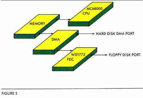
Now, if we were on a normal computer system, there would be four addresses we could directly PEEK or POKE to twiddle the floppy controller chip. We are not. Atari in its wisdom set the DMA chip right smack between us and the FDC (see Figure 3). So, not only do we have the exciting thrill of hassling with the FDC, we also have to beg the DMA chip to let us talk to the FDC. We'll solve that in a bit. Take a look at Figure 4.
There are four flavors of FDC commands:
Type I commands are essentially move the head," You will be surprised at the variety of ways Western Digital found to move it.
Type II commands are Read/Write sector commands. There are only two, praise be.
Type III commands deal with the disk at the track level. They are for reading a track, reading the ID marks, or formatting a track.
Type IV commands are Force Interrupts. These are only used when the FDC has gone to sleep and cannot be awakened. However, do not rely on them too much; there are ways to put the FDC to sleep that are permanent until poweroff, and one of the easiest is an improper Force Interrupt. Generally a Force Interrupt is handy during a frozen Read/Write command.
Taking the command types one at a time, I will show the bit pattern for the command, and talk about what the bits do.
TYPE I COMMANDS:
Command    Bit Pattern (7-0)
Restore:   0000 h V r1 r0
Seek:      0001 h V r1 r0
Step:      00lu h V r1 r0
Step In:   010u h V r1 r0
Step Out:  011u h V r1 r0
Restore moves the head to track 0. Seek moves to a given track number. Step In and Step Out step the head once in the direction indicated, and Step steps the head one track in the direction previously established by Step In or Step Out. The individual bits are as follows. The function is performed if the bit is ON:
u: Update the Track Register Reflects the current track. This means you will be able to read the Track register from the CPU to find out what track the FDC is on.
h: Motor-On Flag. This means that before anything happens, the FDC will turn on the drive's motor and wait six revolutions of the diskette to let the diskette get up to 300 RPM before anything happens. You will also find h on other commands. It saves the programmer the agony of wondering if the disk is up to speed.
V: Verify Track. When the step is completed, the FDC will read a sector mark from the disk and compare the track number written on the disk with what it thinks the track number should be. If they don't match, either the disk is weird or the FDC is out of whack with the disk. Caution: a strange disk (such as a copy protected disk) will often have weird track numbers deliberately written into the sector marks. And a disk that is blank will have no track numbers at all.
wait about 32
microseconds after
doing a
Force Interrupt while
the FDC wobbles
drunkenly
awake.
r1, r0: Step Rate. The floppy-disk drive head can only move at a certain speed between tracks; r1, r0 selects this speed. It works like this:
00: 6 msec per track (use this for 5 1/4-inch disks)
01: 12 msec (no need)
10: 2 msec (kind of fun for 3 1/2-inch, but not reliable)
11: 3 msec (the usual for 3 1/2-inch, unreliable for 5 1/4-inch)
The specifications given in the Developer's Toolkit from Atari are just
plain wrong about these step rates. Use the above figures. Generally, stick
with 11 for 3 1/2-inch drives and 00 for 5
1/4-inch drives.
Typically, you don't ever use the Step. Step In, or Step Out commands. Use Seek and maybe Restore.
Seek works like this: The FDC thinks it is on track #(TRACK register). It may be wrong because of switched drives or other confusing phenomena. If it is wrong, best correct its thinking by stuffing a number into that register before the Seek. Then, put into the DATA register (#3) the number of the track to which you want to go. Then, issue the Seek command and wait around until the Busy bit of the STATUS register goes away. The FDC is done.
Restore is another handy command. It cares little about where the head is, but pulls the head in until the Track zero line goes low. Restore is helpful after a read/write error because if there's dust on the head it cleans the dust off by moving the head a long way across the disk. Also, if the disk head has wobbled, Restore gets the FDC's TRACK register and the actual head back together.
Something Western Digital didn't think of: There are two drives and one TRACK register The drives are usually on different tracks. Hence, anytime you switch drives, you must store the current track for this drive somewhere, fetch the current track for the new drive from somewhere else, and put it into TRACK, Otherwise, the FDC will get out of sync with the new disk. Atari BIOS routines handle this by reserving some locations for the stored track number Look at $A08 and $A0C on ROM-based ST systems.
TYPE II COMMANDS
Fortunately, there are only two commands to worry about here. They are Read and Write Sector They look like this:
Command       Byte# (7-0)
Read Sector:  100m h E 0 0
Write Sector: 101m h E P a0
Our old friend h is still here. Use him if you're not sure if the drive is up to speed, which is almost always. The new bits are:
m: Multiple Sectors. Usually you don't do this. If 1, the FDC will read or write sectors starting at the sector number you give it until you Force Interrupt the controller out. This is really a marvelous way to hang the controller. If you are very, very good, you can use this to read an entire track in one rotation of the diskette, like Atari's people did, but beware.
E: Settling Time (30 milliseconds). Assuming you just stepped the head, Setting this bit tells the FDC to wait 30 milliseconds to give the head time to stop rattling-a good idea. (You also can do this during the Step by turning on the verify bit, but that has,other problems.)
P: Enable Write Precompensation. I was hoping not to get into this, but.
When you write all those magnetic fields onto a disk, you get the same effect as if you had made a line of bar magnets. North and south poles of two magnets attract, and north and north poles of two magnets repel. This causes your bits to literally wander on the diskette. At read time they can get so far away from where they should be that the data separator cannot follow them.
So, we have Write Precompensation that writes two north-north magnets slightly closer together and two north-south magnets slightly farther apart. This way bits repel, attract, and end up at roughly the correct position. Write Precompensation is not really necessary for single density, but you will want it in a big way for the double density used by the ST. So keep this bit on when writing.
a0: Data Address Mark. Remember our Beginning of Data Field mark ($FB) which appears at the beginning of each sector's data? (see Figure 2). You have the option of using $FB (which you should do), or writing a deleted data mark, which just offers a fairly dumb way to mark, at operating system level, whether or not a sector is part of an erased file. If you set this hit, you will write an $F8 instead of an $FB, and every time you read the sector, a status bit will be set telling you this is a "deleted" sector This causes problems. Summary: Don't.
To read or write a sector, first set the SECTOR register and TRACK register so that they will match the sector and track data found in the sector header (Otherwise, the FDC will insist "Record Not Found"; it checks both.) Next, issue the Read command, and watch the fireworks.
There are some kludges to go through to set up the DMA chip that I will
discuss later.
FIGURE 5
| STATUS REGISTER DESCRIPTION | |
| BIT NAME | MEANING |
| S7 MOTOR ON | This bit reflects the status of the Motor-On output. |
| S6 WRITE PROTECT | On Read Record: Not Used. On Read Track: Not Used. On any Write: It indicates a Write Protect. This bit is reset when updated. |
| S5 RECORD TYPE/SPIN-UP | When set, this bit indicates that the Motor Spin-Up sequence has completed (5 revolutions) on Type I commands. Type II & III commands, this bit indicates record type. 0=Data Mark. 1=Deleted Data Mark. |
| S4 RECORD NOT FOUND (RNF) | When set,, it indicates that the desired track, sector, or side was not found. This bit is reset when updated. |
| S3 CRC ERROR | If S4 is set, an error is found in one or more ID fields; otherwise it indicates error data field. This bit is reset when updated. |
| S2 LOST DATA/BYTE | When set, it indicates the computer did not respond to DRQ in one byte time. This bit is reset to zero when updated. On Type I commands, this bit reflects the status of the TR00 signal. |
| S1 DATA REQUEST INDEX | This bit is a copy of the DRQ output. When set, it indicates the DR is full on a Read Operation or the DR is empty on a Write operation. This bit is reset to zero when updated. On Type I commands, this bit indicates the status of the IP signal. |
| S0 BUSY | When set, command is under execution. When reset, no command is under execution. |
TYPE III COMMANDS
These are track-level commands. One of them, Write Track-also known as formatting the track-is used all the time. Do this 80 times with a Step in between, and you've formatted the disk!
The Read Address command reads the next address mark on a track and returns it to you. This is a great way for finding out exactly what is on a track, particularly if the track is damaged. If you repeat this command over and over you'll get a list of all living sectors on track. Usually this is nine sectors times six bytes, or 54 bytes.
Read Track gives you a fairly accurate dump of the entire track, all 6,000-odd bytes, so have a big memory area waiting to receive data. It generally manages to foul up anytime the data separator resyncs at the beginning of each sector, and sometimes drops a byte out of the blue. It is a handy tool for examining a track that has utterly died, but is not reliable enough for day-to-day use.
Write Track, as mentioned, formats the track. Again, it takes around 6,000 bytes to do this. One way is to set up a memory table 6,000 bytes long and feed it to the FDC as each byte is requested. Atari does it this way. Another method is to set up a bunch of nested loops and do it in code (note how many repeated bytes there are in Figure 2). This is fine, but your code has to be darned fast to work, because the FDC will ask for a byte once every 32 microseconds. Even the 68000 doesn't need any distractions when trying to transfer data at that speed, so shut off interrupts while you are doing direct disk I/O. By the way, the DMA controller handles I/O on the ST, and is immune from interrupts.
During formatting, the Floppy Disk Controller takes special action on any $Fx byte and writes special marks to the disk. For instance, when you feed the FDC an $FB, it writes an $FB with a clock byte of $C7 instead of $FF It also starts the CRC calculator running. ($FB is the beginning-of-data mark, remember) An $F7 input byte results in the FDC writing two CRC bytes with no $F7 in them at all. Hence, remember this rule: Any byte input to the FDC during Write Track (format) that begins with an $F is going to do something weird.
"don't do anything;"
+0 volts means
"begin."
The reasons for
this are lost in
antiquity.
This is why you can't do a Read Track, then a Write Track with the same data to clone a track. First, Read Track will not always give you the right sector data, and it will definitely screw up the beginnings of sectors. Second, Write Track does funny things with $Fx bytes, including bytes you find in the middle of a sector; you cannot format data into a sector with $Fx's in it. Instead, format a blank track, then copy the data. If you're fast on your feet, you can issue nine Read Sector commands in one track revolution, then nine Write Sector commands in one revolution. Or, if you're brave, you can use the Multiple Sector Read/Write.
Follow the formatting command with a Read Sector for all the sectors on the track to see if there are any bad spots on the disk. A CRC error means a bad spot.
According to the Atari BIOS manual, formatting the data fields with zeroes is bad karma to the operating system. Besides, it doesn't test the disk very well. Use a repetition of $6DB6 instead. This places maximum stress on the north-north and north-south magnetic field patterns. The operating system will take care of initializing the sectors for boot, directory, and so forth after formatting. Read a freshly-formatted IBM disk sector and you will find $6DB6.
TYPE IV COMMANDS
There is really only one Type IV command: Force Interrupt. Western Digital gives you a bunch of options on how to interrupt the controller (immediately, after index pulse, by next Christmas...). Most of these are completely unused. The thing to do is:
Force Interrupt Right Now: 1101 1000, then, 1101 0000. This usually wakes the controller up. (The $D8 is an Immediate Interrupt and the $DO is a Clear The Immediate Interrupt.)
You must wait about 32 microseconds after doing a Force Interrupt while the FDC wobbles drunkenly awake. Do anything faster and you will shut down the interrupt and really euthanize the FDC.
Do the Force Interrupt whenever anything fails in a floppy disk read/write. Atari does it all the time. It's the "resetl770" subroutine.
STATUS REGISTER
The STATUS register (see Figure 5) gives you eight bits of wildly exciting information about the last command you did. Generally, it reflects information about stepping commands. But you never can tell. If you need to get the status, do a Seek from the current track to the current track. This is a no-operation command, but it sets the STATUS bits correctly. Atari does this in their BIOS to leave the FDC in a known, Type I status state.
You can read STATUS after a sector read/write to look for deleted data marks, CRC errors, and so forth. But wait 32 microseconds after the Busy bit goes away before looking at STATUS. Otherwise, the FDC may not have yet updated the STATUS byte.
The bits look like this:
S7 Motor On
If 1, the MOTORON output to the drive is on. If zero, it is not.
S6 Write Protect
On a Write operation, 1 indicates that Write Protect is active and
you can't write to the drive.
S5 Record-type/Spin-up
Type I command: 1 = MOTORON spinup complete. Type II, III command:
1 = You just read a deleted data mark. Why?
S4 Record Not Found error
1 = You tried to read a sector that was not there. The FDC gave up
after 5 revolutions (1 second). If you think the FDC is lying, best check
the TRACK and SECTOR registers.
S3 CRC error
A 1 usually means you had a bad data-CRC in the data area; the disk
has problems. However, if the RNF bit (above) is also set, you have a bad
CRC in the sector header, which is usually gruesome to fix. Note that you
can often repair a bad data CRC by rewriting the sector. See above discussion.
S2 Lost Data/Track 00
Type I command: 1 You are on track 0. Type II, III command: 1 You did
not get back to the FDC fast enough to read a byte it wanted to hand you,
or you did not give a byte as fast as it
wanted. This means your data I/O loop is too slow (I warned you!),
or it could mean you forgot to turn the interrupts off and the 68000 got
distracted. Remember: 32 microseconds per byte, and that means not very
darn many 68000 instructions.
S1 Data Request/Index Pulse
Type I command: This reflects the index-pulse pin. If you read this
in a tight loop, it will usually be 1, but every 1/5 of a second it will
briefly go to zero. Type II, III command: 1 = The FDC either wants a data
byte right now or it wants you to read one right now. If you're doing "polled
I/O," you sit and watch this bit, and whenever it goes high, you read or
write a byte.
S0 Busy
1 = A command is underway. Don't joggle my elbow. Note that this does
not set for 32 microseconds following input of a command, so you had better
wait awhile after issuing a
command before testing Busy, or it will not reflect Reality.
Generally, you will do a sector read/write, read in STATUS, and mask off the bits that are useless (everything except Lost Data, CRC, Write Protect, or RNF error), then look for any nonzero value equaling disaster.
CORRECTIVE ACTION WHEN READ/WRITE BOMBS
If the read/write bombs, first retry the command up to four times. (CP/M systems retry ten times, which ought to tell you something.) It may work on retry because of dust on the head rubbing off, phase of the moon, electrical transients, witchcraft, or thin spots in the disk oxide.
If that doesn't work, restore the head back to Track zero, then move it back to the track you were working on and try again. This resettles the head on the correct track in case it drifted, and rubs goo off the head. Try this whole procedure twice; it often works. Retries are a fact of life even with diskettes in perfect conditions. Build them into your code and count on them.
THE DMA CONTROLLER
We have mentioned that Atari placed a DMA chip between memory and both the hard disk and floppy disk controller. The DMA chip can kick the 68000 off of memory long enough to do data transfers, and it is essential for the speed required when using a hard disk (see Figure 3).
Learn to live with the DMA chip if you want to program the FDC. You can only access the FDC through the DMA chip, and the DMA chip also handles data I/O to the FDC.
To program the DMA chip:
-
Clear the FIFO (First In, First Out), a 32-byte buffer, or 'holding pond,"
in the DMA chip which is used to inhale chunks of data at a time. It must
be cleared before new data goes in. (This 32-byte buffer can play hell
with the ID-Mark Read command, which only transfers six bytes. They will
not make it to memory. After an ID-Mark Read, read in three or more ID
Marks to force the data through the buffer.)
-
Tell the DMA chip you're going to be reading or writing by how you do step
#1: For Read use $90,$190,$90, and for Write use $190,$90,$190.
-
Tell the DMA chip how many 512-byte chunks you're going to transfer (This
will be sectors in the case of Read/Write Sector, but also applies to track
reads of 6,000 bytes.)
-
Ask the DMA chip to let you talk to the FDC registers.
-
Set the Floppy Drive Controller registers (TRACK and SECTOR) as necessary,
by first asking the DMA chip to let you talk to a specific register, and
then sending data to that register.
-
Ask the DMA chip to let you talk to the FDC command registers.
-
Issue the command to the FDC.
-
Wait for the FDC to finish the command by looking at its IRQ line which
goes to zero when the FDC is done. Conveniently, you can sample IRQ with
the MFP chip (bit 5).
-
You're done. So poll the DMA chip to see what it thought of the transfer.
Was there a DMA error? No? Good. Bit 0 of DMA STATUS should be nonzero.
- Ask the DMA chip if you can poll the FDC. Poll the FDC status register to see what the FDC thought. Was there an FDC error? No? Good. The various status bits should all be zero.
$80: COMMAND/STATUS register
$82: TRACK register
$84: SECTOR register
$86: DATA register
Then, put the value you want sent to the FDC into the DISKCTL register of the DMA chip, and it'll make its way to the FDC.
The FDC is just not fast enough to keep up with the 68000 on anything, so you must surround all accesses to the FDC with delay loops. You will find these at the bottom of listing for the program, TRAKREAD, enclosed on your START disk. They can be most valuable.
ATARI'S FDC BIOS
Atari wrote a great deal of software to run the floppy disk. It is sent to all developers as FLOPS in the BIOS listing. Because you must access the FDC through the DMA chip-which is an Atari-only part-an examination of this software is essential. There is little or no documentation about the DMA chip. The only place you can look to learn is the floppy disk driver in the BIOS.
wisdom set the DMA
chip right smack
between us and the
FDC.
The TRAKREAD program on your START disk uses Atari's own BIOS routines. (Atari gave me permission to reprint them, thank heaven.) I weeded out things that were not essential for the task at hand (such as the Vertical Blank handler) and shortened, straightened, and commented the code for your reference.
I use Atari's calling protocol for everything because, when you switch from this program to the real BIOS, everything will remain consistent.
I've also modified Atari's Read-Sector routine to do Read-lD Mark and Read-Track, then called the Read-lD and Read-Track. The calling sequences tell all about the request, and can be modified if you should wish to.
THE PROGRAM
TRAKREAD is written with AS68 Ataris very own assembler. It should be compatible with most in-line assemblers available with the various C packages. Using it is easy. Double click on TRAKREAD.TOS, then insert the disk you wish examined. At the prompts, choose drive A or B; side Front or Back (use Front on single-sided drives); enter the Track number in hex (from $00 to $4F), and the disk will be read. The next prompt will ask you where to dump the information (C for console, P for printer). During the dump, you may press any key to pause; press Control-C to exit to the Desktop.
TRAKREAD does some obvious things, such as using Read-ID and Read-Track commands to scan the ID address marks and data on the track. But it also does a host of less visible things, such as stepping the disk. Take the program apart and examine it closely. It is provided primarily as a concrete example for all the theory we've been discussing. We've covered a great deal of material in this article. I don't know about you, but I'm happy to bring it to a close.