TUTORIAL
SOFTWARE ENGINEERING
Module Madness
BY KARL E. WIEGERS
After receiving a Ph.D. in organic chemistry, Karl Wiegers decided that it was more fun to practice programming without a license. He is now a software engineer in the Eastman Kodak Photographic Research Laboratories. He lives in Rochester, New York, with his wife, Chris, and the two cats required of all ST-Log authors.
Can you believe it? After only three (count 'em) months of discussing how to analyze a computer-oriented problem and design a software solution for it, we're almost ready to begin writing some programs. Seems hard to believe that we're making so much progress, but it's true.
Forgive the slight sarcasm. I know some of you are probably frustrated that I've been holding you back from the keyboard for so long, but it's for your own good. I've been trying to impress upon you the benefits you can reap if you follow a software engineering approach in your own program development. While some small projects may not seem to warrant all this trouble, there's never anything wrong with making sure you know exactly what problem you're trying to solve before you start hacking away at it. This is just as true of computer programming as it is of woodworking.
But we really have made progress, and I hope you've begun using at least some of these software engineering concepts yourself. Like any other tool, they should be applied judiciously. The overall goal is to bring a measure of structure and discipline to your program development that may have been lacking in the past.
A Brief Rehash
In the first two installments in this series, we took a close look at the primary step of modern software development, the process of gathering requirements and writing a detailed specification. This document may be in the form of a so-called "structured specification," which uses data-flow diagrams to graphically depict the movement of data among processes, data stores and objects external to our system. A data dictionary also is built, in order to keep track of all the individual pieces of information associated with our system and their logical (and hierarchical) groupings.
Last month we took an initial look at how to translate a structured specification into an executable computer program. The process of structured system design results in a plan for satisfying the specifications revealed during the analysis phase. Overview design considers the more abstract facets of our plan, while the detail design step gets into the nitty-gritty aspects of what each piece of our system is going to do. A "piece" of the system is now a program module, which corresponds to a primitive process on one of our lowest-level data-flow diagrams.
The internal structure and function of each program module is described in a "process narrative," or minispec, which can be written using a variety of techniques. We looked at minispecs written for the same process using a flowchart, pseudocode and an action diagram. (Personally, I favor action diagrams.) What we didn't get to yet is how we fit all these modules together into a well-structured, hierarchical computer program. Read onward.
Program Building Blocks
I assume that you are already fluent in at least one computer language. It really doesn't matter much which ones, but I hope you have some familiarity with a modern structured language such as C, Pascal or one of the newer flavors of BASIC available for the Atari ST. Such languages share some common features, one of which is that they encourage you to subdivide your large programs into a bunch of smaller, self-contained pieces. These pieces are called procedures in Pascal and some BASICs, functions in C, and subroutines in FORTRAN and other BASICs. I will refer to all such entities as "modules." A module is basically a named, addressable (that is, callable) piece of computer code.
There are lots of good reasons for building a program from many small modules rather than as a single monster source file. We discussed some of these advantages last time. We also talked a little bit about some of the characteristics of good modules. These included being short, relatively simple, focused on a single purpose, independent from other modules, and having access to only that subset of the entire system's data that is actually required. We'll talk more about some of these ideas in a little while.
One thing we didn't get to last time is how you fit all of your little modules together to build the final program. Unlike construction toys, you can't just fit any old pair of pieces together. The data interface established for each module places some restrictions on how one can be connected to another. And it's also important to arrange your modules in some kind of hierarchy, so that it's clear which module can call another module when necessary.
Charting Your Course
A "structure chart" is often used to depict the hierarchical connections among the modules in a system. A sample structure chart appears in Figure 1. As usual, this figure refers to the educational chemistry game, Reaction Time, that I wrote for the 8-bit Atari computers. Bits and pieces of Reaction Time have been scattered throughout the preceding articles in this series.
Each box on a structure chart represents a separate program module.
The box labeled "Main" at the top of the chart represents the main program in the Reaction Time system. The main program is the big boss of modules, which is why it appears at the top of the chart (just like a corporate president). The primary function of the main is to invoke (or call) other modules whenever it needs to. Modules at a level below the main are "subordinate" modules; conversely, the main is the "superordinate" of those modules. This same sub/super relationship can be seen farther down the page in Figure 1, where some of the subordinate modules themselves call other, even lower-level modules.
Each of these modules should correspond to a bubble (process) on a dataflow diagram from your structured design. As an exception, the main procedure often is not shown explicitly on a DFD, since its principal function is to control which of the processes that really does the work gets switched on at any particular time. The main really might not do any of the inputs-to-outputs data transformations we've come to expect from the processes in a data flow diagram.
In fact, there is a more formal way to depict the behavior of a "control process" like this. Control processes often are used for real-time software applications, such as using the computer to control a piece of electronic equipment. Maybe we'll take a look at control processes one of these days.
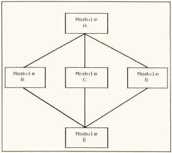
The lines connecting the modules on a structure chart indicate which higher-level module can call which lower-level (subordinate) modules. More often than not, a particular high-level module can call several subordinates, each of which performs a different function. On the other hand, multiple lines going to the same subordinate from several superordinate modules indicates that the subordinate can be invoked in several different ways, from different higher-level modules. Figure 2 shows that Module A has three subordinates, but Module E has three superordinates.
Some other information can also be shown on the structure chart, using little arrows with either solid or open circles on the end. The open circles represent data that is passed from the module at the tail of the arrow into the module at the arrowhead. The arrows with solid circles indicate the movement of "control" information from one module to another. For the sake of clarity, I've shown just a few of these little arrows in Figure 1.
Control information can be things like status flags, return codes and so on. For example, a module whose function is to see if a particular disk file exists might return to its superordinate a control item indicating that the file exists and is open, exists and is closed, or doesn't exist. Of course, these "flags" are actually data items (variables), but their purpose is to control what happens next, rather than to actually move interesting information around from place to place. Hence, control flows like this are sometimes treated separately from ordinary data flows.
You will recall (I hope) from our earlier discussions that you really can't infer anything about the sequence in which different processes take place from a dataflow diagram. (The only exception is when a particular process requires a data flow from a data store; the process that places something into that store obviously must take place before the process that uses the data.) Structure charts give us more information about the sequence in which modules might be executed. For example, in Figure 2, Module A must be executed before Modules B, C or D, which in turn must be executed before Module E. However, to learn more about whether Module B, C or D goes first, you'd have to look at the process specification for Module A.
Module Coupling
In the past few issues, I've used the term "data interface" many times. Maybe I should explain this now, as we begin to delve more deeply into the inner structure of modules. A data interface is nothing more than a definition of the information that's shared between two modules. This definition can be on a strictly abstract level, as with the data stores that I stuck between every pair of processes on the data-flow diagram during structured analysis. Or, it can be at the most concrete level, as when you're defining the byte-by-byte contents of a disk file or the details of a complex record structure.
FIGURE 1 - Structure chart for Reaction Time.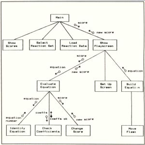
The main point to keep in mind is that each module should have access only to the information it requires for proper functioning: no more and no less. This is part of the software engineering precept of "information hiding." In plain terms, if a module doesn't have access to a particular chunk of data, it can't change the data. This becomes particularly valuable during program debugging. If all parts of the program have access to the data exhibiting the problem, it can be extremely difficult to track down the statements that are doing the damage. However, when only a limited number of modules could possibly be introducing the faulty information, you can focus your debugging efforts on just those modules.
The extent to which the modules in a software system share data is sometimes referred to as "module coupling." Modules are said to be "tightly coupled" if there is a great deal of data shared between them, whether or not this degree of data connection is really needed. On the other hand, "loosely coupled" modules share only that data which is truly required by all of them.
As a matter of good program design, module coupling should be kept to a minimum. This is consistent with our goal of maximizing module independence. It also reduces the likelihood that a change or problem in one module will inadvertently cause peripheral damage elsewhere in the program. Loose coupling also makes it easier to regard each module as a separate entity so that it can be reused in other programs—a highly desirable goal.
The very crudest form of data interface is, in fact, to have no data interface at all. This is the case in Atari BASIC programs, in which all variables can be used and changed anywhere within the source file. A GOSUB offers no protection, because Atari BASIC doesn't really have true subroutines, in the sense of them being separate procedures, modules or files. The existence of "global" variables like this is something you really want to avoid. You've probably had the experience of spending hours on debugging only to discover that variable J was being changed someplace you didn't expect it to be. Fortunately, since our present discussion assumes you are using a language that permits modular programming, this ghastly situation shouldn't be much of a problem.
Content Coupling. If one module somehow directly accesses data (or program statements) inside another module, the modules are "content coupled." This is really no better than the totally global, un-modular situation I mentioned in the previous paragraph. You should avoid content coupling at all costs. It intertwines the two modules involved so much that you really don't gain much by writing that part of your program as two separate modules. This is a case of very tight module coupling. With any luck at all, your favorite programming language won't even let you get away with this.
Common Coupling. "Common coupling" is essentially a limited case of the global variable situation. In many languages, you can declare that a particular group of variables be shared among a specific set of modules. This is accomplished using an EXTERNAL statement in PL/I, an EXTERN variable declaration in C, a COMMON statement in FORTRAN, and a SHARED or COMMON statement in some kinds of BASIC. Common coupling takes place when the group of common variables defines some kind of a data structure. We encountered the term "data structure" before in our discussion about data dictionaries; this is essentially the same idea. Another example of common coupling is when two or more modules access the same data file.
In common coupling, all of the modules are referencing the same block of memory locations in which the elements in the data structure are stored. Each module is dependent upon the preset sequence of variables in the structure, and a change in that structure affects every module that references the structure Also, common coupling contradicts our plan of giving each module access to only the data it needs, since every module has access to the entire shared data structure, whether it uses it all or not. One module could accidentally change some of the original data when it's not supposed to which might make your debugging sessions feel like a life sentence. Avoid common coupling whenever you can.
External Coupling. This is a looser form of coupling than common coupling, in that only a single data element (as opposed to an entire data structure) is shared among several modules. External coupling is a little better than common coupling, since the sequence of items within the structure is no longer a factor, and since each module is accessing only that part of the structure that it needs.
The use of pointers in the C language is essentially a form of external coupling. Pointers give the called function access to specific variable storage locations, so the values of those variables can be both used and changed. This is called passing data "by reference," since the pointer is "referring" to the actual address at which the data item of interest is stored. You have to be extra careful when passing data by reference.
There are many times that external coupling is the most compact, efficient way to pass information from one module to another. So, sometimes it makes sense to use it. Just make sure you remember the ramifications, and be careful when you do get involved with external coupling. Sometimes module efficiency is less important than good overall software design.
Control Coupling. The next loosest type of module coupling is called "control coupling." This refers to the situation in which one module somehow controls the functioning of another.
A common instance is the passing of a control "flag" from one module to another; the called module uses the state of that flag variable to determine what it is supposed to do. While this is useful when used properly, it does run contrary to our plan of insulating the internal workings of each module from all other modules in the system. Obviously, the module passing a flag into another module must "know" something about what the second module does for a living, or the flag wouldn't mean much.
Stamp Coupling. I don't really understand why this term is used, but it's in the literature, so we'll use it too. Stamp coupling exists when several modules reference the same non-global data structure. For example, suppose module A reads a record from a file and passes the entire contents of that record into module B for processing. Modules A and B are stamp coupled. This isn't such a bad situation, but you have to remember that any change in the structure of the file (or, in general, of the passed data structure) will affect both modules.
Data Coupling. Now we're getting to the very loose end of the module coupling spectrum. Modules are data coupled if the only data communication between them is by passing individual data elements (not structures) in an explicit argument or parameter list. That way, only the data that really needs to be shared between the modules is exchanged, and any change in the physical grouping of individual data items really doesn't cause any problems.
Data elements (which could be single-valued variables or arrays) are typically passed in this way through a CALL statement, or through a function reference in C. The argument list in these cases defines the data interface between the modules. This is an example of passing data by value, as opposed to the case of passing data by reference that we mentioned earlier. Passing arguments by value is much safer, because the original values of the arguments can't be changed. The function or procedure being called simply assigns the values of the variables in the argument list to a parallel set of variables that are local within the subordinate module. This may seem wasteful of memory, but remember that the goal is to maintain the independence of each module. Data coupling is a good way to do it.
Of course, some modules have no direct coupling at all, if they don't operate on the same sets of data. I'm sure you can think of many examples from your own programming experience. And it's also likely that a given pair of modules may exhibit several of the kinds of coupling I described here. In that case, the "official" coupling level is the tightest, or highest level of coupling they exhibit.
The purpose of this discussion is not to make you memorize a bunch of arbitrary new terms. I just want you to be aware of the different kinds of interconnections that can crop up among the modules in a software system. Since our goal is to minimize module coupling wherever we can, it helps if you can keep in mind the various sorts of connections that might exist. The effectiveness of your modular, structured program design will be enhanced when you have the lowest possible coupling between the modules in every superordinate/subordinate pair.
Module Complexity
Throughout our software engineering discourse, we've concentrated on the idea of breaking a software problem down into elemental pieces that can be dealt with in an organized, manageable way. This is basically a divide-and-conquer strategy. The goal of the partitioning process during structured design was to wind up with primitive processes on the data-flow diagrams, each of which performs a single, well-defined function. Your success in partitioning will be revealed by the degree of complexity shown by each individual program module.
Basically, human beings aren't terribly bright. We have a limited ability to comprehend and deal with complex systems. In fact, the only sure-fire approach is to subdivide complex things into a bunch of less complex components. In the case of computer programming, the more complex a particular module is, the more likely you are to generate errors in the course of writing the program code. Since we want to avoid errors (right?), a good start is to minimize the complexity of each individual program building block.
Module "cohesion" is related to the complexity idea. A module's cohesion refers to how closely the module approaches the design goal of performing a single function. For example, a module that initializes some variables, opens a file, reads the file, does some calculations, writes to the file and closes the file is said to have a low "functional strength," in that many different functions are being performed by the module. The other extreme would be to write separate, tiny modules to carry out each of those processes. Each one would have high functional strength (or cohesiveness), but the system architecture (that is, the hierarchical arrangement of the modules) becomes very complex because there are so many pieces to fit together.
A whole spectrum of module cohesion can be identified, similar to the scale of module coupling. Mercifully, I'll spare you all the gory details. But I want you to strive for a high functional strength of each of your modules, by trying to make each one do a single task well. Don't throw diverse functions into the same module just because they fit. If you keep in mind the general goal of keeping modules small (down around 10–100 executable lines of code), you'll be able to think more clearly about how to segregate the various tasks your system must perform into individual program components.
Even if all of your modules do have good functional strength, they may still be quite complex. There are several ways to assess the complexity of a module. How many arithmetic operations does it carry out? How many decision-making statements does it have? How many possible paths are there through the code in the module? Do the best you can to keep the answers to all these questions small.
One Two Three, Go!
At this point, I'm going to skip over the large and very important topic of structured programming. I'm assuming that, as experienced programmers, you are already skilled in the art of writing good, clean, well-structured code Your modules all have only one entry point, and only one exit point. You don't use GOTOs unless you absolutely have to. You indent your source code to make it readable, and you use plenty of comments. You declare all of your variables, whether the language insists upon it or not. You use structured constructs (where available) such as IF/ ELSE IF/END IF and SELECT/CASE statements. And, of course, you document your programs like crazy. Have I missed anything?
So now, since you've been champing at the bit for months, I hereby authorize you to go and write code! Take process narratives in hand, and write all the program modules your system requires, no more and no less. Test them and make sure they work, then put them all together. Test the result, and your project is complete.
Test them? Put them all together?? Test the result??? These are not trivial concepts. Entire books have been devoted to systems integration, program testing and software quality assurance. In our next installment, we'll talk about strategies and tactics for testing your modules, both individually and in concert with their buddies, as well as approaches for integrating your modules into the final software package. In the meantime, think about just what "software quality" means. Once we've tried to define it, we can strive to achieve it.