SOFTWARE ENGINEERING
Program Design Considerations
BY KARL WIEGERS
After receiving a Ph.D. in organic chemistry, Karl Wiegers decided that it was more fun to practice programming without a license. He is now a software engineer in the Eastman Kodak Photographic Research Laboratories. He lives in Rochester, New York, with his wife, Chris, and the two cats required of all ST-Log authors.
"Measure one thousand times, cut once."
This old Chinese proverb suggests that a good way to accomplish a task is to make sure you know what you're doing, then do it right the first time. The time spent on planning, thinking, and measuring more than makes up for the cost of repeating the task because you blew it initially.
"If you don't have time to do it right, when will you have time to do it over?" This old high school chemistry lab proverb means that you might as well take the time to do the experiment properly at the outset, since you don't gain anything by repeating the entire project because of a first-pass screwup.

"Design one thousand times, code once." This modern software engineering proverb (which I made up) means the same thing as the old Chinese proverb. Make sure you're solving the right problem, design the most effective software solution to that problem, try to think of every possible angle, get all the details in hand, figure out exactly what programs need to be written—and then write them, correctly, the first time.
Quite a concept, eh? Well, that's the goal of software engineering. Think the problem out thoroughly before jumping into a source code editor. You really don't want to notice that the swimming pool is empty on your way down from the high dive. And if you follow this precept, you'll find that your programs are much more robust, easier to understand, and easier to change. Unlike a saw cut, you may have to modify a program over and over until you get it right, or until it's such a mess that you have to start over from scratch (see proverb #2).
Reference Material
By now I hope you have bought into the software engineering philosophy for modern computer programming. If so, you might want to start building a library of reference books for additional reading beyond the quick coverage I can present in this series of articles. Run, don't walk, to your nearest technical bookstore and pick up a copy of Roger Pressman's excellent book, Software Engineering: A Practitioner's Approach, Second Edition, McGraw-Hill, 1987. It's worth reading cover-to-cover.
Who's Driving?
The software development methodology I've been describing in the past few months is a "process-driven" or "data flow-oriented" approach to complex program design. That is, we are focusing on the transformations carried out on the data in our system. The information that flows into and out of each process sews the individual processes together into (we hope) a unified whole.
The process-driven approach makes good sense when the emphasis of the software system is to "do" something: perform calculations, animate some figures on the screen, and so on. However, many software applications focus more on the data itself than on the activities performed in the course of running the program. The processes may exist simply to extract the data we want from some repository (like a database), and get it into the form we want for viewing or printing. The interesting part in a system like this is the information itself. Personnel and inventory programs are examples.
A "data-driven" or "data structure-oriented" approach to design makes more sense for this sort of application. The important facts of the design are no longer the details of how one piece of data gets changed into another, but rather the hierarchical structure, links, and relationships among the items of data used by the system. As you might suspect, clever people have invented several conventions for building models of data structure-oriented systems, analogous to those we've been discussing for data flow-oriented systems. We may get into those tools in the future.
A third approach, "object-oriented design" or OOD, is gaining popularity with some software engineers. In object-oriented design, items in the real world that must be dealt with in a software system are treated as discrete "objects," with their own sets of internal and external (that is, as seen by other objects) characteristics. Some computer languages, such as Ada and Smalltalk, are designed explicitly for object-oriented programming. We probably won't try to relate OOD to the Atari world in this series.
Structured Design Levels
In the traditional sequence of software development, design follows analysis (we'll talk about different life cycles for software development one of these days). In the design step, you take the abstract, logical models from analysis (the structured specification), and set about creating a mechanism to implement everything necessary for the final, operational system.
This gradual progression from the abstract to the concrete is intended to insulate you from intimate details when you really want to see the big picture. By way of analogy, suppose you're considering buying a particular house. Your first impression is probably based on a view of the home's exterior in the context of its surroundings. A close look at the heating system ductwork comes much later, if at all. Similarly, your system design should reveal only the degree of detail you really need at any given time.
We can think of two levels of structured design: overview design and program design. The overview design uses data flow diagrams to represent the fundamental functions of the system. Each process on the diagram corresponds to one or more program "modules," rather than representing just an abstract transformation of inputs into outputs, as was the case when DFDs were used for structured analysis. Data stores begin to correspond to actual data files or collections of variables used by program modules, instead of just logical groupings of information.
In the detail design phase, we describe the internal structure and function of each program module. Data flow diagrams aren't very useful for this purpose, so other tools are used. If you've ever drawn a flowchart, you've done some detail design; we'll look at other techniques, as well.
Finally, after detail design is completed and you're convinced that everything is hunky-dory, you can begin the coding phase and actually type out BASIC, C, Pascal, or some other kind of code. Try hard to resist the temptation to immerse yourself in code prematurely. You'll thank me for this advice one day.
An interesting aspect of modern software engineering, as opposed to the historic code-and-fix-until-it-sort-of-works approach, is the large front-end loading of effort. To the casual programmer, it seems as though you really aren't "working" unless program statements are streaming from your fingertips. Not so. If the goal is to have a properly functioning program, every minute of time you spend thinking, planning, and critiquing will pay off in the final product. Trust me, I'm a doctor.
Tools of Overview Design
We've already discussed the important tools of overview design: data flow diagrams and data dictionaries. These are the same methods used in structured systems analysis. The only real difference is that, rather than building an abstract or logical model of our system, we're laying the foundation for a real-life software system that can be implemented in some particular computer environment.
Here's a quick refresher course on data flow diagrams (DFDs). DFDs can contain four kinds of objects: processes, externals, data stores, and data flows. The context diagram is the top level diagram. It represents the entire system as a single process and shows all the objects outside the system that interface to it in some way. Additional diagrams are drawn through a process of stepwise decomposition of the context diagram, showing increasing detail at each lower level of child diagrams. Remember that DFDs don't give you any information about the sequence in which various processes might be executed. They simply show the movement of data throughout the system and the kinds of transformations the data undergo.
The data dictionary is a repository of information about all of the objects in your system. Each object on a DFD should have a corresponding entry in the data dictionary, describing what that object is or does. A hierarchical notation can be used to illustrate the grouping of individual data elements into data flows and stores. The DFDs are valuable for ensuring that your system can accomplish what it's supposed to; the data dictionary is important for maintaining the consistency of names, meaning, and characteristics of each piece of information processed by your system.
The end product of the functional decomposition process you perform during structured design is a bunch of low-level processes, sometimes called "primitive" processes. Each primitive is identified by a numbering scheme that represents its parentage. For example, process 3.1.4 is a child of process 3.1, which is itself a child of process 3.
Modular Construction
A software system ultimately is made up of a number of small program "modules." The word "module" has specific meanings in particular computing environments; I use the word here to mean simply a named, addressable piece of software code. Some languages use terms like "subroutine," "function," or "procedure" to refer to program modules. These are all the same sort of beast, although their detailed characteristics may vary. Modules are the building blocks from which complete programs are constructed.
In the olden days, prior to the advent of computer languages that lend themselves to modularity, programs were monolithic monstrosities, sometimes containing thousands of lines of code all packed together into a single file. 8-bit Atari BASIC is an example of such a primitive language. You can get awfully frustrated if you really want to do structured programming and all you can use is Atari BASIC. You can make some progress by organizing the functions of your program into separate subroutines and using the GOSUB command skillfully. But this is a poor substitute for a truly modular program, with individual procedures that can be compiled separately and linked together as needed.
The primitive processes in the lowest level data flow diagrams created during structured design correspond to individual program modules. This is why the partitioning task carried out during analysis and design is so critical: we want to end up describing the software system to be built in terms of many small, independent pieces. Partitioning should be continued until each process (and hence module) performs a single well-defined function. Of course, the definition of "single function" is up to you, but that's the goal.
Next time, we'll look in more detail at the characteristics of "good" program modules. For now, let me just mention a few general ideas to keep in mind. You should work on the partitioning process until the lowest-level processes will translate into modules having these desirable features:
- Each module should be short. A reasonable target is from 10 to 100 executable statements.
- Each module should have good internal "cohesion." This refers to the logical integrity of the module's function, meaning that the purpose of the module is well-focused on a specific task.
- Each module should be independent of all other modules. When you assemble a complete program from a bunch of modules, one module shouldn't have to know anything about the internal functioning of another. This brings up the idea of module "coupling," which we'll discuss next time.
- A module should access the minimum amount of data. A well-defined data interface for each module is required to sew them together into a final program. This idea flies in the face of the "global variables" characteristic of BASIC and some other unstructured languages.
- A module's complexity should be minimized. If the behavior of the module is so complex that it requires considerable explanation to comprehend, you might be better off subdividing it into a family of smaller, more understandable modules. Ever notice how much easier it is to understand short paragraphs than long ones, no matter what the subject matter?
These rules about modules have several purposes. One is to make your program more understandable by human beings, which becomes critical any time the program needs to be changed—the old maintenance bugaboo. Also, by creating large programs from lots of little programs, we increase the chances of being able to reuse a module we already have sitting around. The concept of reusability is the most important key to maximized programming effectiveness.
Tools of Detail Design
Two tasks remain to be performed at this stage of the design. First, we must somehow represent the internal functions of each primitive process in enough detail that someone can actually write a computer program to carry out those functions. The internal details of a process are described in a document variously called a "process narrative," "process specification," or "minispec," among other names. And second, we need to illustrate how the various primitive processes (modules) are linked together. The DFDs show the information that can move from one process to another. But now we want to depict the hierarchical relationship of the modules. One way to do this is by drawing a "structure chart," which we'll discuss in our next installment.
Process Narratives
The purpose of the process narrative is to give enough detail so that someone skilled in the art of programming (as opposed to the science of software design) could write a module to properly carry out that process's appointed duties. You see, we're gradually bridging the gap between the abstract (what's the problem?) and the physical (here's the solution). However, we still wish to keep the logic and actions to be performed in each process separate from the exact code that will be used in each module. In fact, at this point in our design, it is still not essential to know what computer language will be used. Now let's look at several ways to write process narratives.
Flowcharts. You're probably familiar with the flowchart. This graphical method has been used for many years to represent the details of logic and execution sequence in a program. A sample flowchart is shown in Figure 1. This example, like the others in this article, is drawn from my chemistry game "Reaction Time," written for the 8-bit Atari computers in assembly language.
Several symbols commonly appear on flowcharts. The rectangle simply indicates some process to be performed, such as reading a file or performing a computation. The diamond represents a decision, in which the next action to be taken depends upon some condition. The lines moving from one object to another indicate the sequence in which actions will be performed. Other symbols are used to represent things like printed output, disk files, and so on, but we can skip all that.
The flowchart has the advantage of being visual, which can make it a more effective communication method than reams of text. However, it's difficult to derive a clean program structure from inspecting a flowchart. Where are the loops? How should the IF/THEN blocks be coded? Which IFs are nested inside other IFs? Such things often are not obvious without carefully studying the flowchart.
Flowcharts do have their uses, one of which is diagramming the detailed logic of a complicated procedure. However, they also have many deficiencies. They don't lend themselves well to programming in modern structured languages, such as Pascal and C. For example, it's not easy to use a flowchart to indicate decision making when more than three possible outcomes exist. This sort of task is handled by SELECT/CASE constructs in many languages. Overall, there are better methods for representing the internal functions of processes than flowcharts.
FIGURE 1 FLOWCHART EXAMPLE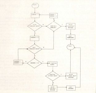
Structured English or Pseudocode. These two terms refer to pretty much the same thing, so I'll lump them together under the "pseudocode" moniker because it's a neater sounding word. Pseudocode is a technique for representing the internal details of a process in a very readable yet structured way. An example of pseudocode is found in Figure 2, which represents the same part of the Reaction Time program that is shown in Figure 1's flowchart.
Notice the program-like structure of the pseudocode illustration. This is not an accident! The hierarchical structure (as indicated by the indentation), and the keywords used in the pseudocode statements are chosen so as to bear a similar structure to the program that will be written eventually. This again helps bridge the gap between the logical and the physical aspects of system development.
While in principle the pseudocode really should be independent of the computer language that will be used during the coding phase, people tend to make their pseudocode look like their favorite structured language. I prefer REXX, which is a very nicely structured language used on IBM mainframe computers, somewhat similar to Pascal. It's perfectly fine to throw in ordinary English text to describe the functions of the module when writing pseudocode. You may have guessed this from the "Structured English" term.
There really aren't any hard and fast rules for pseudocode. Basically, whatever makes the most sense to you (and to whomever has to read your documentation) is just fine. The method you select should be able to represent the three basic structured programming constructs, however. As you may recall, these constructs are:
- Sequence—simply taking one action after another, in the order in which they appear in the program.
- Selection—choosing from several possible actions to be taken, based on some condition.
- Repetition—repeating a specific set of operations until some condition is met.
The detailed syntax for each of these constructs differs from language to language. For example, the selection construct can appear as IF/THEN, IF/ELSE IF/ELSE/ENDIF/, SELECT/WHEN/OTHERWISE/ENDSELECT, SELECT/CASE/CASE ELSE/ENDSELECT, and so on. Any one of these approaches could be used for the pseudocode equivalent in your process narratives. Repetition uses keywords like LOOP, DO, or REPEAT. And, of course, simple sequential processing is indicated by a list of instructions (or English phrases) all at the same level of indentation.
It's a very good idea to use indentation to indicate the hierarchy of logic within the process. I like to use explicit ENDDO and ENDIF statements to conclude a DO or IF logic block, and I align the beginning and ending statements of such blocks so that it's easy to read through the logic.
Your pseudocode conventions can be anything you like, but be consistent. Even though you aren't using an official programming language, you still should choose some rules and stick with them. The basic idea, of course, is effective communication, as with all of the structured techniques we've been discussing. Another programmer should be able to read your process narratives and understand what is going on. And if you're really lucky, you might be able to simply hand a stack of process narratives to somebody who will do all the typing for you: a coder. (Of course, there are those who feel more fortunate being on the coding end, rather than having to struggle with design. Each aspect of the software development process has its rewards.)
Notice how Figure 2 looks a lot more like a computer program than Figure 1, even though they represent exactly the same process. I find the logical structure of pseudocode much easier to translate into an actual programming language than the two-dimensional structure of a flowchart.
Action Diagrams. Another technique for writing process specifications is the action diagram. Action diagrams can be used for either overview or detail design representation, although I tend to stick with data flow diagrams for overview designs. In a sense, action diagrams can be thought of as a more formal sort of pseudocode, in which a bracket notation is used to indicate specific instances of selection, repetition, and simple sequential operations.
FIGURE 2 PSEUDOCODE EXAMPLE
BEGIN: Which_Reaction Procedure
IF first compound matches any first reaction_compound THEN
   IF other three compounds match other reaction compounds THEN DO
         get reaction number
         IF this reaction number is not already done THEN DO
               print "correct" message
               call UPSCORE procedure
            END DO
         ELSE print "already done" message
         END IF
      END DO
   ELSE
      IF this is the last reaction to check THEN DO
            print "incorrect reaction" message
            call DOWNSCORE procedure
         END DO
      END IF
   END IF
ELSE
   DO
      print "incorrect reaction" message
      call DOWNSCORE procedure
   END DO
END IF
END: Which_Reaction Procedure
|
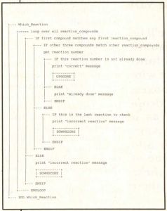
Figure 3 shows an action diagram for the same process that appeared earlier in flowchart and pseuducode forms. A program module is drawn as a bracket; I like to put the name of the module at the top of the bracket and an "END module" notation at the bottom. If you read down the contents of the bracket from top to bottom, each entry represents operations to be carried out sequentially. Brackets can be nested to show how other procedures might be carried out conditionally. If this module calls a lower-level module, the latter is shown by putting its name in a box and placing the box in the appropriate spot in the bracket. This tells the reader, "you don't need to know exactly what happens inside this other module, but you could go look at its own action diagram for details whenever you're ready."
Loops (that is, sequences of operations that are repeated) are shown in action diagrams by placing a double horizontal line at the top of the bracket enclosing the repeated instructions. Sometimes the double line will appear at the bottom of the bracket instead, indicating that the condition for terminating the loop is tested at the end of the loop rather than at the beginning. The simple FOR/NEXT loop in BASIC always tests at the top of the loop; this is like a DO WHILE command in some languages. A loop expressed like this might never be executed. A loop that tested at the bottom (DO UNTIL) is always executed at least once.
Other techniques are also useful for describing the internal functions and logic of individual modules. Some of these are Nassi-Shneiderman charts, decision tables, and decision trees. If you want to read more about such methods, an excellent reference is Structured Techniques for Computing by James Martin and Carma McClure (Prentice-Hall, 1985).
Putting it All Together
Let's see where we stand now. Our system has been thoroughly analyzed, and a structured specification was created using data flow diagrams. Our overview design has shown us a viable software solution to the problem, and the detail design step left us with a bunch of process narratives describing the internal functioning of each program module. We know the modules will fit together properly, because we continually referred to the data dictionary while writing the process narratives.
Now we need to think about assembling all of our modules into some logical whole. We already know what each module does, and we know the nature and structure of the data manipulated by each module. In keeping with our hierarchical approach to program design, we need to arrange the modules into some structure, so we can see who calls whom. A handy technique for showing the hierarchical connectivity of the modules in a program is the "structure chart," which we'll take a look at next time. In addition, we'll discuss some more characteristics of good modules and ideas to keep in mind about the relationships among different modules. Stay tuned....