Commodore On-Line
by Stephen Reed
|
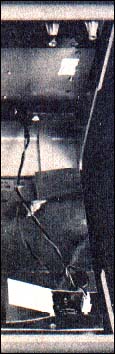
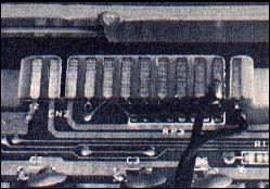
| Power LED cable |
|
| Keyboard cable connection (entwined wiring) |
Many Commodore 64 owners want more from their home computers than the manufacturer can provide. Innovations, adaptations, simplifying--the list is endless.
The purpose of this new department is to serve as a source to users who want technical information about their C64. Hardware and software will be covered in a wide variety of applications and interests.
However, hardware projects presented in this department on occasion will involve opening the C64 cabinet. Please note: this will VOID Commodore's warranty.
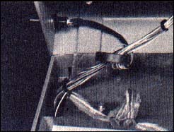
|
| Location of reset switch |
Anyone who works often with assembly language programming understands the frustrations of putting the machine into some endless loop where the only way to escape is by turning the computer completely off.
Of course, this action forces the user to reload all of the object files before giving another try.
This issue describes how to install a hardware reset switch to the C64 that will reset the system NO MATTER WHAT THE SYSTEM IS DOING. The benefit of such a switch becomes clear for debugging as using the reset will not destroy memory.
Don't Forget the Screwdriver
Necessary for this procedure are the following tools: a low wattage soldering iron, some fine gauge resin core solder, a Phillips screwdriver and wire stripper/cutters. Also needed is a momentary contact pushbutton switch and a two-conductor molex-type connector pair. These can be purchased at most electronics stores for less than $5.
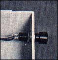
|
| Reset switch to molex connector assembly |
Opening the C64
First, disconnect the C64 from the rest of the system and turn it upside-down on a soft surface to prevent scratching the keycaps. Remove the three Phillips screws from the bottom of the case, put the screws aside and turn the C64 upright.
Now, open the cabinet from the bottom -- there are hinge-like formations on the front of the cabinet to make opening exceptionally easy.
Locate and unplug the power LED cable -- this connection will be in the lower-right hand corner of the case. Remember how the connector is positioned for later reassembly.
At this stage, unfasten the keyboard cable connection in the upper-left hand corner. Remove the upperhalf (keyboard) of the cabinet.
Switch Installation
Drill a mounting hole in the keyboard-half of the cabinet for installing the reset switch. The hole size should be determined by the size of switch.
|
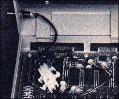
| Shorting wire soldered to user port |
Locate the switch on the lefthand side of the cabinet about an inch down from the top and an inch from the back. Drill a hole and insert the switch for a test fit. Be sure everything is correct before going any further.
Cut a piece of two-conductor wire about five inches long. Strip the ends of both wires, solder them at one end to the molex connector, crimp and insert the molex pins into the plastic housing.
The next step is to pass the wire through the hole in the cabinet so the reset switch can be soldered. Don't worry about polarity as this modification is simply a short and it doesn't matter which wire goes where.
After-soldering, install the switch in the cabinet.
Now, place the keyboard assembly aside and get the computer housing. Place it in front as if it were going to be used. On the lefthand side of the back is the user port (see page 355 of the Programmers Reference Guide). Counting from the right, we will be shorting pins (lines, connections, whatever) one and two together to force a system reset.
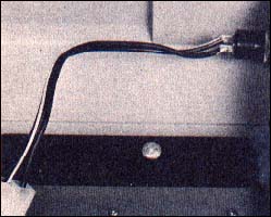
Cut another piece of two-conductor wire and connect one end to the mate of molex connection previously used with the switch. The other ends of the wire are soldered to the back of the edge connections on pins one and three.
|
| Reset switch via molex to user port connection |
Final Test
To test the work, connect the computer to the video and power supply without the keyboard and turn the system on. After the screen has come up, short the wires together. The screen will flicker and the system will reset in about a second. If this does not happen, recheck the work.
Finally, get the keyboard assembly, connect the reset connector, keyboard connector and power LED connector. Put the cabinet together and replace the screws in the back of the housing.
This procedure now offers a master override to force a system reset at any time.
Next issue: Hate blue letters on blue? On-Line, will try black on White -- just like reading a book.
Editor's note: HI-RES invites readers' contributions and questions. Please address correspondence to Commodore OnLine, HI-RES Magazine, 280 W. Canton Ave., Suite 310, Winter Park, Fla., 32789.