Put A Printer On The Atari Ports
C. Kingston
White Plains, N.Y.
In order to use a printer other than the two 40 column models that plug directly into the serial port on the Atari, the Atari owner must either buy an Interface Module or find some alternate method of communicating with the printer. A suspicion that a method of using the joystick ports for general I/O purposes might be found was partially confirmed when a commercial cable and program became available to drive a printer through joystick ports 3 and 4. Although getting the commercial cable would be the easy (albiet expensive) way to proceed, I felt that more could be learned about the Atari by designing and building one. After a lot of digging or information on the Atari, the pieces fell together and resulted in a cable and program for the Atari that would run a printer operating out of the joystick ports. This article provides the necessary information so that the reader can construct a similar cable for a printer, or use the joystick ports for general I/O.
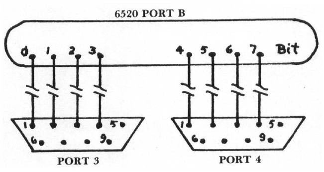
First, a little information about the Atari joystick ports. These use the two eight bit I/O ports of a 6520 PIA chip. Joystick ports 1 and 2 share one of the 6520's eight bit ports (Port A), and joystick ports 3 and 4 share the other 6520 port (Port B - this is the one we will use for the printer). Pins 1-4 of the 9-pin D connector of joystick port 3 are connected to bits 0-3 of PIA port B; pins 1-4 of joystick port 4 are connected to bits 4-7 of the same PIA port. Diagram 1 shows this arrangement.
Port B is addressed by Atari locations $D301 and $D303. Port A is addressed by locations $D300 and $D302. Unfortunately, the conrol lines associated with these ports are apparently not available to the user. With this limitation, the joystick ports can easily be used for general I/O purposes. A 6520 port uses the two registers to control the specific function of the port bits. For port B, location $D303 is the control register, which we will call PCR. Location $D301 is the data or data direction register, which we will call DDR. Note that DDR has two functions. When it is functioning as a data direction register, it allows us to select which bits of the data are to be input and which are to be output. A 0 in the data direction register selects the input mode, while a 1 selects the output mode. When it is functioning as a data register, it inputs or outputs the appropriate data bits when connected to a peripheral device.
We select DDR as a direction register by setting bit 2 of PCR to 0; we select DDR as a data register by setting bit 2 of PCR to 1. So the sequence for setting Port B up as an output port is as follows:
- Put $30 in PCR (Make DDR a direction register)
- Put $FF in DDR (Make all bits output)
- Put $34 in PCR (Make DDR a data register)
Note that $30, rather than $00, is used as the base byte or PCR. This is to maintain the normal operating mode of the Atari, which presumably uses the control lines for purposes other than the ports (the bits other than bit 2 are used for other control purposes). If you wanted to make the port an input port, which it is for the joysticks, put $00 in DDR in step 2. Specific bits can be made either input or output by making the associated direction bit a 0 or 1 respectively in DDR in step 2. Note that the bits are pulled to +5 volts when set for input. Leventhal's book (6502 Assembly Language Programming) has instructions and several examples on using the 6520 chip (in Chapter 11), and the reader is referred there, or to specification sheets, for further information on the operation of the 6520 PIA. Pin 6 of each joystick port is connected to the joystick trigger. The trigger or port 4 is read at location $D013. Only the least significant bit is used, so the value is either 1 (trigger not pressed-line pulled high) or 0 (trigger pressed-line grounded). We will use this for hand-shaking.
The plan of action begins to become clear — or does it? We simply connect Port A to the printer and connect the trigger pin to the outgoing Busy line on the printer. Then we'll connect the Strobe pulse to, uh. There's the rub; we don't have an extra output line available in joystick ports 3 or 4. We could bring, another joystick port into action, but this would be wasteful. Well, what about bit 7, which is only used for parity or special purposes. If we can get along without it, then we can use it for the strobe, and indeed, this is what we'll do. It must be kept in mind that special operations of the printer that may use bit 7 cannot be invoked if we do this.
Now a direct connection between the Atari and the printer would seem to be acceptable. This may be the case if twisted pair cable is used and good grounding practice is followed. I have been using a direct connection off of the KIM-1 application port to drive a printer for some time (the PIA is not a 6520 though). But it appears not to be acceptable if only two or three ground connections are used, which keeps the cable reasonably simple, and the printer uses pull-up resistors for the input lines. My guess is that the 6520 cannot sink enough current to, drop the lines to a respectable level for a 0, thus leaving them near the transition voltage. Any induced hum or noise can then cause a fluctuation between 0 and 1 on the lines. And induced hum or noise can then cause a fluctuation between 0 and 1 on the lines. And indeed, a direct hookup produced a machine gun like output of the same letter as the strobe line was apparently bounced up and down by 60 cycle hum. One answer to this is to use buffer chips or transistors to adequately drop the lines for a 0 output. Because of their availability, inexpensive PNP transistors (2N3906 or 2N5139, etc.) were chosen. Diagram 2 illustrates the complete cable.
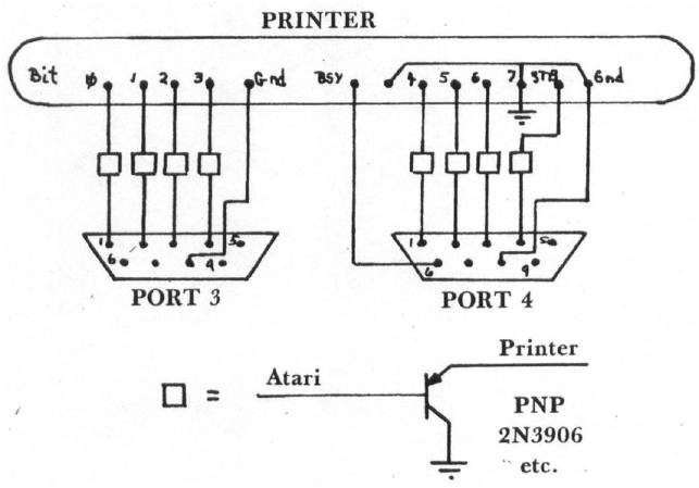
Note that the connections to the transistors from the Atari ports must be as short as possible. The connections on the one I built are about one inch long, and the transistor board sets on the table under the ports. Also note that bit 7 on the printer must be tied to ground. The entire cable should not cost more than $25, probably much less with careful mail order shopping.
A simple software driver applicable to any 6502 based computer could be used to drive the printer. However, if we want to take advantage of the Atari's flexibile I/O system, the program must be written specifically for this purpose. The program in this article was written so that it will hook into the operating system (OS) and operate in place of the normal OS printer subroutines. It is located at $067A-$06FE, which is an area that will presumably be left alone by Atari software so that it will remain available for users' programs.
The Atari controls I/O by means of a set of routines in the Central I/O Utility (CIO). Almost all I/O calls go through the CIO, which is why the Atari has such flexibility in its handling of I/O. A section of the OS ROM is dedicated to the routines which perform the I/O operations. These routines are called through I/O Control Blocks (IOCBs), which in turn transfer operation to the required routine segment (Handler) by using a vector table (Handler Vector Table). (There are eight IOCBs, and thus the Atari can have eight active I/O devices at any one time.) The key to the use of the handlers is the Device Table, which is transferred from ROM to RAM on system initialization. This table contains an identifying letter for each device along with the address of its handler vector table. We can therefore change the address in the Device Table to point to our own handler vector table, which we can set up in RAM. The program in this article sets up a printer handler vector table at locations $680-$68E, which points to the handlers starting at $690. Note that the vectors point to the handler routine address minus one. The vector table address in the device table for the printer (located at $31B-$31C) is changed to point to our handler vector table. The IOCB set up for the printer therefore directs the program to one of our handlers rather than to the Atari OS handlers for printer operation.
One problem is encountered in such an arrangement: the device table is re-initialized whenever the system reset button is pushed. Unless we can put our handler vector table address back into the device table at that time, we would have to do a separate re-initialization step. Fortunately the OS system reset sequence uses certain page zero vector locations for initialization purposes. One is for cassette operation initialization (CASINI at $0002-$0003), and one is for disk operation (DOSINI at $000C-$000D). Depending upon which we are using (disk or cassette) we can set this vector to point to a short routine that re-establishes our handler vector table address. By also transferring the original content of the page zero initialization vector, we can then send the program off to do whatever it was originally supposed to do so that everything will operate properly. The following brief description of the operation of the parallel printer handler shows how these facts are incorporated into the program.
The six bytes at $067A-$067F control the driver's hookup to the OS after a system reset. The bytes labeled LO and HI are used to store the initialization entry location (for the program - or cartridge - that will use the printer driver), which is read from $000C-$000D (DOSINI) during initialization. The segment in $0680-$068E is the handler vector table that points to the appropriate subroutine in the driver (address-1). The byte of $068F is used as a counter for the line length. The subroutine 'OPEN' sets up the 6520 PIA port B as an output port. The subroutine 'WRITE' is the actual printer driver. The byte at $06D2 determines the line length, and is set to the desired number of characters per line plus one. As written, the program is set for a line length of 78; the byte is set to 79 ($4F). It can be set for any line length up to 254.
The printer driver looks for the Atari code for RETURN, which is $9B, and converts it to the ASCII code of $0D. This is the only ATASCII (Atari ASCII) code that is decoded by the driver. The ATASCII and ASCII codes for letters, numbers, and most punctuation and symbols are the same, and other conversions do not seem necessary. The driver assumes that the strobe is high to low. If your printer strobes from low to high, change the following:
06B9 A0 00 0033 LDY #$00
06BB 29 FF 0034 AND #$7F
06C0 09 80 0036 ORA #$80
If your printer automatically outputs a line feed after a carriage return, change $06D7 from $0A to $00.
The segment at BINIT is the initialization subroutine. This sets $000C-$000D (DOSINI) to point to the handler setup subroutine, and puts the original content of DOSINI in LO-HI. If you are not using DOS, then change $06E3 and $06EF from $0C to $02, and $06E8 and $06F3 from $0D to $03. This sets the program up for cassette operation and initialization. If you are using the driver with BASIC, you can initialize it by using the USR instruction pointing to BINIT (1761 decimal). This supplies the necessary PLA command for the USR instruction. If you initialize it from a machine language program, do a JSR to INIT ($06E2). If you are using a disk to load the printer routines, wait until the disk drive shuts off before initializing the driver. For some reason that I have not tracked down, initializing the driver while the disk drive is running seems to inhibit it from turning off. There is no problem here once the printer driver initialization is complete.
The segment HANFX is the one that re-establishes contact with the OS. This is run during initialization, and is called after a system reset. The only way to remove the driver from operation is to turn the computer off or change DOSINI (3000C-D), or CASINI ($0002-3) for cassette operation, back to the values in LO-HI.
Once initialized, the driver will operate with all BASIC commands that drive the regular printer routines. It will also work with all machine language programs that use the I/O control blocks to drive the printer routines. You may have to clear the printer and return the carriage to the left by outputting a RETURN (using the command 'LPRINT' in BASIC) after initialization. This will depend upon the particular printer that you are using. If you write a machine language program that outputs to a printer, it will interface to either the Atari OS handlers or the one here if you go through the IOCBs. However, using the IOCBs requires a bit of programming to set up the proper parameters. It is simpler to directly use the driver routines without going through the CIO. This seems to be what is generally done on most other microcomputers. In that case however, the program will not operate a printer connected to the serial port.
To use the parallel handler directly in a machine language program, the handler program must be loaded into $67A-$6FE. Then it must be initialized by a JSR INIT. This locks it into the system. Before using the printer, the port must be initialized by a JSR OPEN. Then each character to be printed is placed in the accumulator (A) followed by a JSR WRITE. At the completion of the printed material, do a JSR CLOSE (this only puts out a CR, and may not be necessary depending upon the printer used and the program). A skeleton program would look like this:
START JSR INIT
      JSR OPEN
MAIN . . .
     . . .
     LDA CHAR
     JSR WRITE
     . . .
END JSR CLOSE
JMP EXIT
You must be careful in assuming that a machine language program that supports printer output uses the I/O Control Blocks (IOCB's). For instance, the driver was written using the assembler for the Atari by Quality Software. This program does support printer output, but it does not use the IOCB's completely. The actual output that sends the character for printing calls the Atari WRITE handler directly. The calling address must be changed in such a case to point to the WRITE handler in this program.
There is no reason that the joystick ports cannot be used as pseudo RS-232 ports as well, and thus for printers or other peripherals that require serial I/O. I expect to be writing a program for this in the near future in order to connect a digital input pad. One problem in the Atari for this may be the use of interrupt processing subroutines by the OS; these may throw off any timing loops used for serial control. This might force one to inhibit the interrupts, or to use the timers in the Atari for timing control. Who knows, maybe the Interface Module isn't really necessary for flexible I/O with the Atari.
              0002     PON
              0003     ORG   $67A
              0004 * PRINTER DRIVER
              0005 * C * KINGSTON (1980)
067A 20 F4 06 0006 REENT JSR HANFX
067D 4C       0007       HEX 4C
              0008 LO    DS  1
              0009 HI    DS  1
0680 8F 06 A8
     06 DE 06 0010 HANTABHEX 8F06A806DE06
0686 A8 06 DE
     06 DE 06 0011       HEX A806DE06DE06
068C 4C 78 EE 0012       HEX 4C78EE
              0013 CTR   DS  1
0690 A9 30    0014 OPEN  LDA #$30
0692 8D 03 D3 0015       STA $D303
0695 A9 FF    0016       LDA #$FF
0697 8D 01 D3 0017       STA $D301
069A A9 34    0018       LDA #$34
069C 8D 03 D3 0019       STA $D303
069F A9 80    0020       LDA #$80
06A1 8D 01 D3 0021       STA $D301
06A4 A0 01    0022 ALCLO LDY #$01
06A6 60       0023       RTS
06A7 A9 0D    0024 CLOSE LDA #$0D
06A9 C9 9B    0025 WRITE CMP #$9B
06AB D0 02    0026       BNE PRT
06AD A9 0D    0027       LDA #$0D
06AF A2 04    0028 PRT   LDX #$04
06B1 AC 13 D0 0029 BSY   LDY $D013
06B4 D0 F9    0030       BNE PRT
06B6 CA       0031       DEX
06B7 D0 F8    0032       BNE BSY
06B9 A0 80    0033       LDY #$80
06BB 09 80    0034       ORA #$80
06BD 8D 01 D3 0035       STA $D301
06C0 29 7F    0036       AND #$7F
06C2 8D 01 D3 0037       STA $D301
06C5 8C 01 D3 0038       STY $D301
06C8 C9 0D    0039       CMP #$0D
06CA D0 0E    0040       BNE TEST
06CC A2 80    0041 DELAY LDX #$80
06CE CA       0042 DEL   DEX
06CF D0 FD    0043       BNE DEL
06D1 A9 4F    0044       LDA #$4F
06D3 8D 8F 06 0045       STA CTR
06D6 A9 0A    0046       LDA #$0A
06D8 D0 D5    0047       BNE PRT
06DA CE 8F 06 0048 TEST  DEC CTR
06DD F0 C8    0049       BEQ CLOSE
06DF D0 C3    0050 BACK  BNE ALCLO
06E1 68       0051 BINIT PLA
06E2 A5 0C    0052 INIT  LDA $0C
06E4 8D 7E 06 0053       STA LO
06E7 A5 0D    0054       LDA $0D
06E9 8D 7F 06 0055       STA HI
06EC A9 7A    0056       LDA #REENT
06EE 85 0C    0057       STA $0C
06F0 A9 06    0058       LDA #>REENT
06F2 85 0D    0059       STA $0D
06F4 A9 80    0060 HANFX LDA #$80
06F6 8D 1B 03 0061       STA $0318
06F9 A9 06    0062       LDA #$06
06FB 8D 1C 03 0063       STA $031C
06FE 60       0064       RTS
SYMBOL TABLE
  REENT 067A  LO    067E  HI    067F
  HANTAB0680  CTR   068F  OPEN  0690
  ALCLO 06A4  CLOSE 0647  WRITE 06A9
  PRI   06AF  BSY   06B1  DELAY 06CC
  DEL   06CE  TEST  06DA  BACK  06DF
  BINIT 06E1  INIT  06E2  HANFX 06F4