Atari's "Hidden" Character Modes
Sheldon Leemon
Atari's graphics modes are much more flexible than many programmers realize. The Atari keeps a list of numbers to tell itself which graphics mode to display, and you can change these numbers to suit yourself. Try these example programs to see how to create realistic lowercase letters and colorful high-resolution graphics.
The GTIA chip (or CTIA in early Atari models) is the heart of your computer's graphics system, but it can't do the job on its own. Another chip, called ANTIC, feeds instructions to the GTIA. The ANTIC chip is like a video microprocessor. It has its own set of instructions, like a mini-language, to let you program a variety of screen displays. For example, you can mix any two graphics modes on the same screen or even several modes simultaneously.
This set of instructions for the ANTIC chip is called the display list. It's basically a video program. Each instruction controls one vertical portion of the screen, from one to eight scan lines. The display list is set up for you by the operating system in graphics modes 1 through 12, but much more flexibility is possible.
By altering the existing display list with a series of POKEs, you can combine any graphics modes onscreen at the same time. The key step involves changing the display instruction, which is a number from 2 to 15. The display instruction number tells the computer which graphics mode to display on that part of the screen.
However, the display instruction number used by ANTIC does not directly correspond to the number of the graphics mode. For example, to display a line of GRAPHICS 0, you wouldn't POKE a 0 for the display instruction; you'd POKE a 2. Likewise, POKEing a 6 orders up one line of GRAPHICS 1; POKEing a 7 makes one line of GRAPHICS 2, etc. Notice how the display instruction numbers 3, 4, and 5 were skipped? These instructions let you access graphics modes that are not available any other way in Atari BASIC. What kind of modes do these numbers produce?
These special modes are not documented in the usual Atari manuals. Instead, you must turn to the Atari Hardware Manual. This manual, along with the Operating System User's Manual, has been available from Atari and can be found at some computer dealers. It's fairly technical, but it does outline some hardware features not explained in the reference material supplied with the computer.
Creating True Descenders
Two short programs following this article help explain the nature of the "hidden" modes. Program 1 demonstrates the first of these modes, designated by Atari as Instruction Register (IR) Mode 3. Notice line 10: The IR number 3 is POKED into bytes 19–26 of the display list, producing a screen which is half graphics mode 0 and half IR mode 3. Next, the whole character set is printed in both modes (line 30). Finally, the program prints a few adjacent characters in both modes for the purposes of comparison (lines 40–45).
When this program is run, the IR mode 3 characters at the bottom of the screen appear no different from the GRAPHICS 0 characters at the top. On more careful examination, however, some differences can be detected. First, there is more room between the rows of characters in IR mode 3. The four diagonal graphics characters in the middle of the screen form a diamond shape in GRAPHICS 0, but in IR 3 there is a gap between the top and bottom triangles and in the taller cursor. The second difference occurs only in the last 32 characters of the IR 3 character set. These characters appear to be shifted, so that the top of the character has been cut off and moved below the bottom of the character, invalidating the top row, but simulating a ninth row for these characters.
According to the Atari Hardware Manual, there is a simple reason for these differences. By creating a longer block for these characters, and having some appear at the top of the block and some at the bottom, one can create a custom character set with true descenders for lowercase letters like y and p (a descender is the tail which protrudes below the line on letters such as y, p, and q).
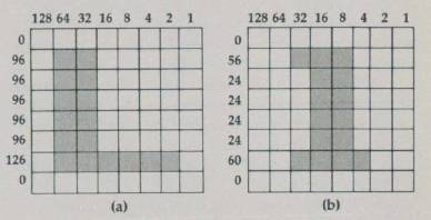
To explain exactly how this mode accommodates these changes, however, we must first review the method by which the computer determines the shape of a character. The data for character shapes is stored in ROM (Read Only Memory), starting at memory location 57344. Each character is represented by eight bytes of data. Since each of these bytes is composed of eight binary digits (or bits), we can picture this data in the form of an 8 × 8 grid.
Figure 1 shows how the data for the upper- and lowercase letter L is translated into the character seen on the screen. In this drawing, each horizontal row represents one byte (the numeric value is given on the left). Each vertical column represents a bit place. A darkened square represents a 1, or "on-bit," in the corresponding bit location (the bit values, which equal the successive powers of 2 from 20 [a value of 1] to 27 [a value of 128] are shown at the top of each column). For example, no squares are darkened in the top row of Figure 1a; therefore, the first byte has a value of 0. In the second through sixth rows, where bits 5 and 6 are darkened, the byte value is 96 (32 + 64); in the seventh row, where bits 1,2,3,4,5, and 6 are darkened, the byte value is 126 (2 + 4 + 8 + 16 + 32 + 64). Finally, in the eighth row, no bits are darkened and the byte value is again 0.
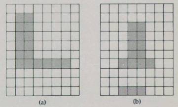
In IR mode 3, however, these same characters are set up in a 10 × 8 grid. Two blank scan lines are inserted below each of the first 96 characters—see Figure 2a. The last 32 characters, which include the lowercase alphabet, receive special handling. When one of these characters is set up in the grid, the first two bytes are shifted down to the bottom two lines—see Figure 2b. This shift of the last 32 characters means that they use the bottom eight lines of the grid, while the other characters use the top eight lines, thus permitting the two bottom lines to be used for descenders.
Multicolor Characters
This leaves us with IR modes 4 and 5 to explore. These are demonstrated by Program 2. Lines 10–20 set up half the screen in IR 4 and half in IR 5. Line 30 prints the full character set in each mode. Line 40 changes the background color for better visibility. The rest of the program lets you use the console buttons to change the color and luminance values of each color register. The SELECT button determines the register, START changes the color of that register, and OPTION the brightness.
These two modes are four-color character modes. The only difference between them is that IR 5 characters are twice as high as those of IR 4. The new Atari 600XL and 800XL computers support these multicolor character modes as GRAPHICS 12 and 13, but the older Atari BASIC on cartridge lacks these modes. The only way to access them on an Atari 400, 800, or 1200XL is to modify the display list with the POKEs used here. Even if you have a 600XL or 800XL, you should stick to this POKE method if you want your programs to run on all Atari models.
Easy Hi-Res Graphics
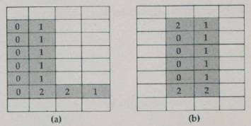
The numbers in the darkened squares indicate the color register used.
The purpose of these colorful characters may not be obvious. When I first saw them while experimenting a couple of years ago, I thought that a three-dimensional effect might be achieved with shading. Then it occurred to me that character modes are useful for displaying not only letters, but also graphics characters. Each of these characters can be used in combination with others to form a bigger picture. This is an easy method for producing high-resolution graphics. Each time you need the drawing, just print a string of characters.
Although Atari provides some graphics characters with the standard character set, you are perfectly free to design your own custom graphics characters. In GRAPHICS 0, these characters are all the same color, and you can achieve the same resolution with custom GRAPHICS 0 characters as you can in GRAPHICS 8 (the normal hi-res 320 × 192 graphics mode). With IR modes 4 and 5, however, these hi-res characters can be created in four colors. I have seen this technique used to create dazzling animation of detailed color figures.
These character modes differ from the others in that each byte of character display data is divided into four groups of two bytes each. These groups determine the color of the four pixels per row. The four possible combinations produce the following colors:
- Neither bit set (00) displays the background color (register 4).
- Right bit set (01) displays the color in register 0.
- Left bit set (10) displays the color in register 1.
- Both bits set (11) displays the color in register 2 for normal characters, and the color in register 3 for inverse characters.
Because two bits are needed to determine the color of each pixel, the horizontal resolution is cut in half. Figure 3 shows how this affects letters in the existing character set. You should be able to verify this effect by changing the color registers in the demonstration program by pressing the console buttons as explained above.
Refer to "COMPUTE!'s Guide To Typing In Programs" before entering these listings.
Program 1: IR Mode 3
IH	5	REM ** SET UP MIXED-MODE SCREEN
GO	6	REM **
EI	10	? CHR$ (125) : X = PEEK(560) + PEEK(561) * 256 + 19 : FOR I = 0 TO 7 : POKE X + I, 3
JC	20	NEXT I : POKE X + 8, 65 : POKE X + 9, PEEK(560) : POKE X + 10, PEEK(561)
HB	21	REM *
OB	25	REM * SET UP COMPARISON CHARACTERS
HG	26	REM *
NO	30	GOSUB 60 : POSITION 2, 17 : GOSUB 60
IO	40	POSITION 10, 12 : ? CHR$ (6); CHR$ (7)
LA	41	POSITION 10, 13 : ? CHR$ (7); CHR$ (6); "L1"; CHR$(160)
DE	45	POSITION 10, 14 : ? CHR$ (6); CHR$ (7) "{5 SPACES}"; CHR$ (160); "L1"
PG	46	POSITION 10, 15 : ? CHR$ (7); CHR$ (6) : POSITION 15, 10 : ? " "
AK	50	POKE 752, 1 : POSITION 2, 9 : ? CHR$ (28)
HE	51	REM *
AN	55	GOTO 55
HJ	56	REM *
GB	60	FOR I = 0 TO 127 : ? CHR$ (27); CHR$ (I); : NEXT I : RETURN
Program 2 : IR Modes 4 & 5
LA	5	REM ** SET UP MIXED MODE DISPLAY
GO	6	REM **
CI	10	? CHR$ (125) : X = PEEK(560) + PEEK(561) * 256 + 3 : POKE X, 69
HK	15	FOR I = 3 TO 8 : POKE X + I, 5 : NEXT I : FOR I = 9 TO 16 : POKE X + I, 4 : NEXT I
GK	20	POKE X + 19, 65 : POKE X + 20, PEEK(560) : POKE X + 21, PEEK(561) : POKE 752, 1 : ? "{UP}"
HB	21	REM *
MO	25	REM * PRINT CHARACTER SETS
HG	26	REM *
GN	30	GOSUB 60 : ? : ? : GOSUB 60 : POSITION 0, 0 : ? CHR$(156) : POSITION 1, 13
HC	31	REM *
HL	35	REM * CHANGE BACKGROUND COLOR
HH	36	REM *
KE	40	FOR DELAY = 1 TO 1500 : NEXT DELAY : ? CHR$ (253) : SETCOLOR 4, 0, 14
HD	41	REM *
CH	45	REM * COLOR REGISTER CHANGE ROUTINE
HI	46	REM *
EE	50	R = 0 : S = 5 : GOSUB 70
DC	52	S = PEEK(53279) : IF S = 5 THEN R = R + 1 - 5 * (R = 4) : GOSUB 70
AF	54	IF S = 6 THEN C = C + 1 - 16 * (C = 15) : SETCOLOR R, C, L : GOSUB 75
BL	56	IF S = 3 THEN L = L + 2 - 16 * (L = 14) : SETCOLOR R, C, L : GOSUB 80
PL	58	FOR DELAY = 1 TO 50 : NEXT DELAY : GOTO 52
EI	60	FOR I = 1 TO 154 : ? CHR$ (27); CHR$ (I); : NEXT I
NE	65	FOR I = 156 TO 255 : ? CHR$ (27); CHR$ (I); : NEXT I : RETURN
GN	70	M = PEEK(708 + R) : C = INT (M/16) : L = M - 16 * C
LC	71	POSITION 2, 15 : ? "REGISTER "; R : GOSUB 75 : GOSUB 80 : RETURN
CM	75	POSITION 15, 15 : ? "COLOR "; C; " " : RETURN
MP	80	POSITION 25, 15 : ? "LUM. " ; L; " " : RETURN