FRIENDS OF THE TURTLE
David D. Thornburg, Associate Editor
Atari Logo-The Plot Thickens
Perhaps it is because I am in the somewhat enviable position of working with four versions of Logo on a daily basis, but I sometimes get concerned about issues that might not bother most people. In the case of Atari Logo, I find myself wishing that I could draw lines with a higher resolution than that available from graphics mode 7. Unfortunately, even though the computer supports many other graphic modes, Atari Logo does not.
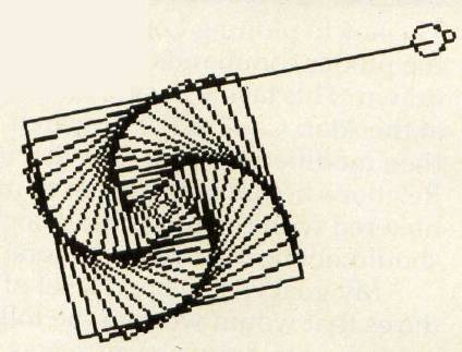
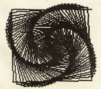
For example, if I draw a closely spaced squiral pattern on the screen, I get a dense and somewhat fuzzy picture like this:
Instead, I would like to get a nice crisp picture like this:
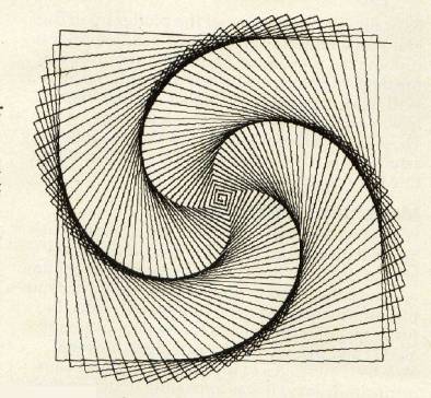
Obviously, since I did get a nice crisp picture, I was able to solve the problem. The trick is to have your turtle graphics pictures drawn with the Atari 1020 color graphics printer. This device is a four-color pen plotter that draws pictures on plain white paper with black, blue, green, or red ball-point pens. As you can see from the picture above, the resolution of this plotter is quite high and the lines are crisp and thin.
Plotter Commands
The key to plotting Logo procedures is to generate the plotter commands as the picture is being drawn. This task was first tackled by Peter Cann at the Atari Cambridge Research Laboratory and then modified by Jason Gervich in Atari Customer Relations before being given to me. Naturally, I tinkered with the procedures some, so the results should not be blamed on anyone at Atari.
My goal was to build a set of plotting procedures that would work in the following way: If a procedure to draw a picture was typed by itself, it would appear only on the display screen. If, instead, the user typed
DRAW [procedurename]
the procedure would be drawn both on the screen and on the plotter. Having two ways to examine a procedure lets you save the plotter for the final debugged version. This saves on pen wear and on time, since the plotter is not nearly as fast as the screen turtle.
The key procedure is shown below:
TO DRAW :LIST
SETWRITE "P:
(TYPE CHAR 27 CHAR 27 CHAR 7)
(PR "M240,0\*I\*M INT 2 * YCOR", INT (-2)*
  XCOR)
RUN :LIST
SETWRITE [ ]
END
Basically, all this does is set the plotter up in the graphics mode and zero the pen position prior to running the procedure. Once the procedure is finished, the plotter is turned off (with the SET-WRITE [ ] command). Note that the line that looks cryptic includes some backslashes (\). These are used to let Logo know that the following asterisks are to be taken literally, and do not indicate multiplication.
Movement And Color
Well, if we just run our procedure, we might ask by what magic the plotter is supposed to know how to draw the lines. The answer is that anytime we move the location of the turtle, we must send this information to the plotter as well. Since the turtle graphics commands for turtle movement are FD and BK, we must create new ones that also send messages to the plotter. Because I am intrinsically lazy, it was appealing to define new motion commands called F and B as follows:
TO F:X
FD:X
PLOT
END
TO B :X
BK:X
PLOT
END
Clearly, from these procedures, you can see that our PLOT is very thin. To thicken the PLOT, we add:
TO PLOT
(PR IF PEN = "PD ["D] ["M] INT 2 * YCOR ", INT
  (-2) * XCOR)
END
This procedure examines the pen position of the turtle along with the turtle location, and sends the plotter pen scurrying to its corresponding position. In order to take maximum advantage of the plotter paper width, I rotated the plot by 90 degrees so that as the screen image moves from left to right, the plotted image moves from top to bottom. This gives a very nice-sized image, even though the plotter paper is only 4.5 inches wide.
Of course, there is always the possibility that you might want to clear the screen. Since this should also move the plotter pen to the origin, we add the command:
TO C
CS
PR "M0, 0
END
Changing the pen color is also easy—especially with these procedures:
TO PENBLACK
(TYPE CHAR 67 CHAR 48 )
END
TO PENBLUE
(TYPE CHAR 67 CHAR 49)
END
TO PENGREEN
(TYPE CHAR 67 CHAR 50 )
END
TO PENRED
(TYPE CHAR 67 CHAR 51)
END
The crafty among you will no doubt find that you can modify these four procedures to change the screen pen and pen colors as well.
Printing Procedures
The remaining plotter procedure that I find useful lets you get a "plotted" printout of your procedure listings:
TO P.PROCS
SETWRITE "P:
(TYPE CHAR 27 CHAR 27 CHAR 14 )
POPS
SETWRITE []
END
I suggest that you enter these procedures into an otherwise empty workspace and save them in a file called PLOTTER. Then, whenever you want to plot the results of your handiwork later on, you can read these into your workspace by typing:
LOAD "D:PLOTTER
and get your masterpiece recorded for posterity.
The squiral pattern at the beginning of this article was obtained by entering:
DRAW [SQUIRAL 91]
in which SQUIRAL had the following definition:
TO SQUIRAL :ANGLE
MAKE "SIDE 0
REPEAT 180 [F :SIDE RT :ANGLE MAKE "SIDE
 :SIDE +1]
END
To see an even more spectacular picture (one that I call a snowflake sunset), enter:
DRAW [SETUP SN 300 9]
in which SETUP and SN have the following definitions:
TO SETUP
PU SETPOS [-150 0] PLOT SETH 90 PD
HT
END
TO SN :S :L
IF :S < :L [F :S STOP]
SN :S / 3 :L
LT 60
SN :S / 3 :L
RT 120
SN :S / 3 :L
RT 120
SN :S / 3 :L
LT 120
SN :S / 3 :L
LT 120
SN :S / 3 :L
RT 60
SN :S / 3 :L
END
On the screen you get this:
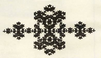
And, on the plotter, you get this:
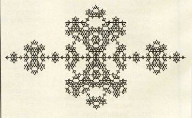
The snowflake sunset is one level of a fractal curve. You can experiment with different generations of this curve by changing the second number when you use SN (for example, SN 30030). For the purposes of this month's column, this curve nicely demonstrates the value of connecting a pen plotter to your Atari Logo system!