Part II
Commodore 64 Video — A Guided Tour
Jim Butterfield, Associate Editor
We now continue our guided tour of the video capabilities of the Commodore 64 computer. Along the way we'll stop for lots of experiments, things for you to type in and ivatch the effects of manipulating this remarkably versatile computer.
The story so far: we're touring the 6566 chip, which gives the Commodore 64 its video. We noted last month that the chip goes to memory for its video information, but can only reach 16K; the computer controls which 16K bank via control lines in 56576 (hex DDOO). Then we picked out the functions of the video control word at 53265 (hex D011).
We've seen the variety of important controls that we can reach in location 53625: vertical screen positioning, screen blank, bit mapping, and extended color. There's a second control location, at 53270 (hexadecimal D016); let's look at it.
The first thing we should note about this location is that the two high bits are not used. That means that we can usefully POKE only values from 0 to 63 in there. It happens that if we PEEK 53270, we'll probably see a number that is 192 too big; if you want to see the working value, use PEEK(53270) AND 63, which will throw away the unused part of the number.
We saw a vertical fine scroll in location 53265. Location 53270 has a horizontal fine scroll that works exactly the same way. Type:
FOR J = 8 TO 15 : POKE 53270,J : NEXT J
You'll see the screen characters slide over horizontally. As with the vertical fine scroll, we also have facilities for trimming the size of the screen. Restore the screen to its original form with POKE 53270,8. Then shrink the screen by typing POKE 53270,0. You'll see a character disappear from each end. In other words, you now have a 38-character screen instead of 40 characters. Don't forget that fine scroll and shrink can be used effectively together.
If you add 16 to the contents of 53270, you'll switch to multicolor mode. This is not the same as extended color which we discussed previously. Multicolor allows selected characters to be shown on the screen in a combination of colors. Extended color, you may remember, allows screen background and foreground to be set individually for each character.
If you're familiar with the VIC-20, you'll find that setting the multicolor mode makes the Commodore 64 behave in the same way. Here's the trick: we invoke multicolor on an individual character by giving that character a color value greater than 7. This way, the regular colors (red, blue, black) behave normally, but the new pastels (grey, puce) switch to multicolor mode.
You'll need to create a new character base to exploit the advantages of multicolor, since the old characters weren't drawn with color in mind. However, we can get a quick idea of the feature by invoking it: POKE 53270,24 sets up multicolor; the screen characters may turn a little muddy, but don't worry about them. Set a primary color such as cyan and type a line. Normal, right?
Next, set up one of the alternate colors (hold down the "Commodore" key and press a key from 1 to 8). Type some more; you'll get multicolor characters. They won't make much sense, since the character generator isn't building the colors suitably; but you can see that something new is going on.
Adding 32 to the contents of 53270 gives chip reset. You won't want to do this very often — it's done on your behalf when you turn the power on. If you do use chip reset, remember that to make it work, you must turn reset on and then off again. POKE 53270,32:POKE 53270,8 will clear you out of multicolor mode.
Setting Screen And Characters
Location 53272 sets the location of screen RAM (the video matrix) and the character generator (the character base). Don't forget that they must be in the same 16K block, as determined by the low bits of address 56576.
You can get the BASIC address of screen RAM in this way: take the contents of 53272 and divide by 16; then throw away the remainder and multiply by 1024, and you have the screen address. You can get the BASIC address of the character base in this way: take the contents of 53272 and divide by 16. Then take the remainder, subtracting one if it's odd, and multiply by 1024; that's the character base address. Both addresses will need to be adjusted to allow for the 16K quadrant we have selected.
Now: if we are in bit map mode, we get the character base address in a slightly different way: divide the contents of 53272 by 16; take the remainder and divide by 8, discarding the remainder; finally, multiply by 8192. That's the bit image; it should be either 0 or 8192.
How does this work out in the standard Commodore 64? We may PEEK 53272 and see a value of 21. That means the screen is at INT(21/16)* 1024, or address 1024. Right on target. The character matrix works out: the remainder of 21/16 is 5, so drop one for the odd number, giving 4; multiply by 1024 to get address 4096. You may remember that our discussion last month indicated that RAM was replaced by the character generator ROM at this video chip address. And when we flipped to bit mapping in the last episode, we still got remainder 5; divide by 8 giving 0, then multiply by 8192 — you still get 01 high resolution screen from address 0.
If you'd like to try your hand at the arithmetic, flip to upper-/lowercase mode (hold down SHIFT and press the Commodore key) and see what addresses have changed. Or if you'd rather, try typing in FOR J = 1 TO 100:POKE 53272,21 :POKE 53272,23:NEXT J and watch the action.
The Raster Register
Location 53266 (hex D012) and the high bit of the previous location are not of much use to the BASIC programmer, but can be very valuable to the machine language tyro. Here's the idea: by looking at these locations, you can tell exactly where the screen is being scanned at that moment. This allows you to change the screen as it's being scanned: halfway down, you could switch from characters to bit map, or change to multicolor, or move a sprite that has already been displayed.
If you're really interested in machine language, you may want to take an extra step: instead of watching where the screen is, you can leave the message "Wake me when you get to scan line 100." ML tyros will recognize this as an interrupt request. How do you set the identity of the desired scan line? By placing it into the same locations, that's how. We have a dual function here: when we read, we recall the scan location; when we write, we store an interrupt value.
Light Pen
Locations 53267 and 53268 (hex D013 and DOM) are the light pen registers. An Atari-style light pen can be plugged into joystick port number one; if it sees a suitable signal from the screen, the X and Y values will be latched into these registers. The light pen can be used on an interrupt basis: we can "stop the music" and get immediate action if we choose to set things up that way.
This is the second time we've mentioned interrupts; perhaps we'd better discuss them a little more closely.
Interrupts
Interrupts are for machine language experts — things happen too fast for BASIC to cope in this area. There are four types of interrupts: raster, light pen, and two kinds of sprite collision. (We'll talk about sprites in Part III next month.) We may use all of them or none; and even when these signals are not used for interrupt, we can check them.
Location 53273 (hex D019) tells us which of the four events has occurred. We don't need to make the interrupts "live"; they will signal us any time the particular event happens. The weights are as follows:
1 (bit 0) — the raster has matched the preset line value;
2 (bit 1) — a sprite has collided with the screen background;
4 (bit 2) — a sprite has collided with another sprite;
8 (bit 3) — the light pen has sensed a signal;
128 (bit 7) — one of the above has triggered a live interrupt.
Once any of the above takes place, the bit will remain stuck on until you turn it off. How do you turn it off? This may sound goofy, but you turn an interrupt signal off by trying to turn it on. Hmmm, let me try that again. Suppose that we have both a raster and a light pen signal; we'll see a value of 9 (8 + 1) in the interrupt register. Now suppose further that we are ready to handle the light pen, so we want to turn its signal off. We do this by storing 8 into location 53273. Huh? wouldn't that turn it on? Nope, it turns it off, and leaves the other bit alone. So after storing 8, we look at the register again, and (you guessed it) we see a value of 1 there. Honest.
Location 53274 (hex D01A) is the interrupt enable register: it sets the above signals for "live interrupt." Select bits 0 to 3 corresponding to the interrupts you want. Whatever live interrupt you select will now trigger a processor interrupt and also light up that high bit of 53273. Don't forget to shut the interrupt flag off when you service the interrupt, using the method indicated in the previous paragraph. Otherwise, when you finish the job and return from the interrupt (with RTI), it will re-interrupt you all over again.
Table 1: 6566 Video Chip C64 Control and Miscellaneous Registers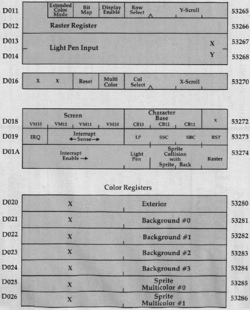
A Little Color
Some of the colors we have mentioned and some we have yet to discuss are neatly stored in addresses 53280 to 53286 (hex D020 to D026). We may store only values 0 to 15 here, for the 16 Commodore 64 colors.
The chart shows it all: the exterior (border) color; then four background colors (they may be selected as part of multicolor characters or bits); and finally, two colors reserved especially for sprites.
Sorry, but we had to be a little more technical this time around. Many of the locations are of value to machine language users; we can't show their features with simple PEEKs and POKEs.
But these locations are powerful, and they are not hard to use once you get a feeling for them.
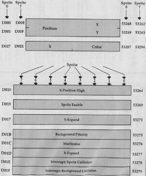
Next time, we'll take a look at sprites and, literally, fit them into the picture. They are great fun.
Copyright © Jim Butterfield