Apple Game Paddles
John K. Elberfeld
Rochester, NY
Understanding the functions of the Apple game paddles was my first step toward interfacing the Apple with the "real world." The simplicity of the paddles is a result of the amazing versatility of the game In/Out connector (where the game paddles are plugged in) on the computer mother board. The Apple Reference Manual, pages 23, 24, 100, and 114, provides the basic facts about the paddles and the connector. This article will attempt to unify these facts into an understandable explanation of the Integrated Circuit electronics used every time Little Brick Out is RUN.
The push button control on the paddles is a normally open momentary switch. No electricity may flow through this switch until it is pushed down. As soon as it is released, the flow of electricity stops. The source of voltage is pin 1 on the game I/O connector, which supplies + 5 volts through the connecting wires to one side of the switch. When the button is pressed and the switch is closed, this + 5 volts passes through the switch and back through the wires to pin 2 on the I/O connector. Pin 2 is connected to a standard Transistor-Transistor Logic (TTL) Integrated Circuit (IC) on the Apple mother board. When + 5 volts is applied to pin 2, this IC causes the memory location of (-16287) or ($C061) to be greater than 128. The actual circuitry allows three push buttons to be used, but this article will supply details for button 0 only.
When pin 2 is grounded, the value of (-16287) will fall below 128. However, not applying + 5 volts to pin 2 is not the same as grounding the pin. To make the pin grounded when no voltage is applied, a 560 ohm resistor is permanently connected between pin 2 and ground. Any electricity which might deceive pin 2 into thinking that 5 volts was being connected to it disappears through the resistor and into the ground. This resistor is located in the 16-pin DIP Header — the black box at the end of the paddle wires. This resistor is small enough to effectively ground pin 2 when no voltage is applied, but large enough so the current through it is very small when + 5 volts is applied.
Figure 1 shows this information.
The game controller analog inputs (knobs which turn) are physically very simple. The following details apply to PADDLE 0, but the concept is the same for all paddles. Just the pin numbers are different.
Figure 1. Push Button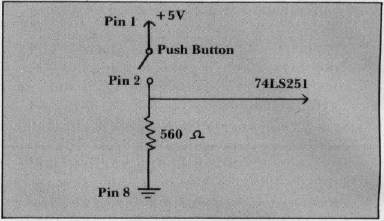
Pin 1 again supplies + 5 volts through the connecting wires to one end of a 150,000 ohm variable resistor. The other end of the resistor is connected through the wires to pin 6. Turning the game control varies the resistance between the 5 volt supply voltage and pin 6 on the game I/O connector. When the resistor is turned so the resistance in the circuit is large, very little current can flow back to pin 6. A low resistance setting of the game control allows a large current to flow back to pin 6.
Pin 6 is a direct connection to a capacitor on the mother board. A capacitor is designed to store electric charge, but this capacitor starts out with no charge. Electric current which flows through pin 6 to the capacitor will build up the charge on the capacitor until it reaches a predetermined level. When the Apple is instructed to read the value of the game control through the BASIC command PDL(0), it uses a machine language monitor routine. This command starts a counting routine, consisting of a loop and a counter, to time how long it takes the electric current through the game controller resistor to charge the capacitor back up from its zero starting charge. The number of times that the computer executes this timing loop is the value reported when PRINT PDL(0) is RUN.
To limit the electric current flow into the capacitor when the game control is applying zero resistance, a small 100 ohm resistor is connected in series between the capacitor and the game controller. If too much current flowed into the capacitor in a very short time, the power supply or other circuits could be damaged.
How can the computer tell when a capacitor is charged? The Apple uses a 558 quad timer Integrated Circuit which is designed specifically to accomplish this. This circuit is similar to four 555 timers on one chip and allows up to four game paddles to be used at one time. The 558 IC is carefully designed to have a high output when the capacitor is charged to less than 2/3 of the supply voltage, and a low output after it reaches 2/3 of the supply voltage.
The timing cycle is started when the 558 is triggered – accomplished by PEEKing at location 49264 (-16272 or $C070). After the 558 is triggered, the output goes high, and the capacitor is allowed to charge up from the current through the game controller. When the capacitor reaches 2/3 of the supply voltage, the output goes low and remains low until triggered again. The 558 then automatically discharges the capacitor and waits for another trigger. Memory location $C064 is high (greater than 128) while the output of the 558 timer is high, and low (less than 128) when the output of the timer is low. How a high output from the 558 affects the value in a memory location is a good topic for some other author.
Figure 2 shows the circuit used for Paddle 0 on the Apple. The other game controllers have similar circuits but different memory locations.
Figure 2. Game Control Paddle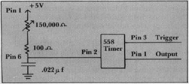
The Apple Reference Manual, Page 144, lists the following monitor routine for reading the value of the game controller. These directions are permanently stored in the Read Only Memory (ROM) of the Apple and are used during the execution of BASIC commands in regular programs. The following explanation assumes some knowledge of machine language programming.
PREAD LDA PTRIG
      LST ON
      LDY #$00
      NOP
      NOP
PREAD LDA PADDL0, X
      BPL RTS2D
      INY
      BNE PREAD2
      DEY
RTS2D RTS
PTRIG is location $C070. LDA to this location triggers all 4 timers on the 558 chip on the mother board. This forces all the outputs of the 558 chip to go high and remain high until the capacitors are charged. This trigger also allows the capacitor to start charging.
LST ON is not a machine language command, but is probably a note to indicate that the timer has been triggered.
LDY #$00 loads the Y register with a value of zero to initialize it for the timing loop.
NOP means no operation. These are dummy commands used to take up some time before the timing loop is entered.
LDA PADDL0, X stores in the accumulator (A) the value of the memory location indicated by PADDL0, with the location address increased by the value stored in the X register. This allows a single routine to time all four allowable game controllers. The number of the controller (0 through 4) must be loaded in the X register before the routine is entered. PADDL0 is the memory location $C064, the memory location which is high when the current through paddle zero has not charged the capacitor. When register X has 0 stored in it, this location is read. When register X has the value "1" stored in it, the value in memory location $C064 + 1 = $C065 is loaded in the accumulator. $C065 is the memory location which is high when paddle 1 is in the process of charging its capacitor.
BPL RTS2D commands the computer to branch to location RTS2D if the value loaded into A is positive. RTS2D contains the command RTS which stops the timing loop and returns control to the BASIC commands which first called in the routine. A byte is considered negative when bit 7, the eighth bit from the right, is "1," and positive when this bit is "0." This seventh bit is also used as the flag to indicate that the output of the timer is still high. While the capacitor is in the process of being charged by the current through the game controller, this seventh bit in location $C064 is set to " 1," the computer considers the value of the entire byte negative, and no branching occurs. The computer continues down the list of instructions. When the seventh bit is "0," it means the capacitor is charged enough, the timing stops with the value in Y indicating the number of times the program executed the loop, and the program branches to RTS2D which returns control back to the BASIC program. This is the normal END for this monitor subroutine.
INY commands the computer to increase the value of the Y register by 1. The Y register is now a counter which indicates how many times the computer passes this point in the loop. It is this value stored in Y which is the "value" of the game controller setting.
BNE PREAD2 commands the computer to branch back in the loop to the location of PREAD2 (the LDA PADDL0, X command) if the value of the Y register is not equal to zero. If the resistance is very high in game controller, the Y register may have counted up to 255, the largest number it can store. (All 8 bits are set to 1). Adding 1 more to 255 does not result in 256, but changes all the l's to 0's (255 + 1 = 0). At this point the computer realizes it has gone too far, and it does not branch back to continue the loop.
DEY decreases the value of Y by one. Since Y must be zero to reach this point in the program, Y changes from 0 back to 255 because 000 - 1 = 255. This is the largest number that may be a paddle reading. At this point the timing loop is halted.
RTS then returns control to the BASIC program which called the subroutine. The value in Y is the value of the paddle reading.
The loop of:
READ2 LDA PADDL0, X  (5 CYCLES)
      BPL RTS2D      (2 CYCLES-NO BRANCH)
      INY            (2 CYCLES)
      BNE PREAD2     (3 CYCLES - SUCCESSFUL BRANCH)
is repeated until the capacitor is charged or until Y reaches a reading of 256 (000). The loop uses 12 clock cycles or about 12 microseconds. The maximum amount of time this program can measure is 255 loops or 3060 microseconds. The time needed to charge sufficiently the .022 mfd capacitor on the mother board through 150,000 ohm game controller is 1.1 * 150,000 * .022 E-06 = .0036 seconds = 3600 microseconds. This extra time guarantees that the maximum value can be reached when the game controller is set for maximum resistance.
Where can this information lead? It is possible to substitute a thermistor in place of the game controller so the reading of a paddle will indicate the temperature. A game controller with a resistance differing from the 150,000 ohm Apple Controller can be adapted to this circuit. A tilt sensitive switch could replace the pushbutton to indicate changes in position. The possibilities are endless and challenging. For more information on these circuits, see:
Mims, Forrest M.
Engineer's Notebook
Radio Shack, 1979
Lancaster, Don
TTL Cookbook
Howard W. Sams, 1974
Semiconductor Reference Guide
Radio Shack, 1981