THE OSI® GAZETTE
Part I:
A Small Operating System: OS65D The Disk Routines
T. R. Berger Coon Rapids, MN
Editor's Note: In this first part of a two-part series, Mr. Berger presents valuable information for all disk drive users. The article concludes next month with a memory map of the disk routines and flowcharts for all the major subroutines. — RTM
In this article I will examine the disk routines in OS65D (V3.2 NMHZ). To understand these subroutines, it is neither necessary to know precise details about the physical functioning of a disk drive, nor to know about various methods of storing data on a diskette. However, such background makes it easier to understand what is involved in an operating system, and why certain processes are done as they are. There are several articles [1-3] which offer very good general descriptions of disk drives. Further, manufacturers' drive manuals usually give fairly complete descriptions of individual drives. I only discuss those aspects which are immediately applicable to the functioning ofOS65D.
The Disk Drive
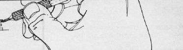
The typical diskette looks as in Figure 1. A magnetically coated round piece of plastic is enclosed in a protective cardboard envelope which has an inner, slippery plastic liner. The hub of the disk drive engages the large hole in the middle of the plastic diskette causing it to spin very rapidly inside its envelope. There is a long slot in the envelope enabling the head of the drive to make contact with the plastic diskette.
Imagine a large number of concentric circles drawn on the plastic diskette so that part of each circumference is visible through the slot. We call each circle a track on the diskette. When the diskette is in the drive, the head is precisely positioned under one of these circular tracks, and contact is made with the diskette. The spinning of the diskette causes this track to continually pass over the head. If we imagine the track to be a continuous loop of magnetic cassette recorder head, we can appreciate how one might store data on the disk. If we envision each track as being a different loop of tape then we can begin to see the power of a disk drive.
In some minifloppies, inserting the diskette and closing the drive door brings the head into contact with the diskette. On other drives, there is a little lever with a soft pad attached directly above the head which is below the diskette. On drives with such a lever, there is a switch which causes this slapping. Turn the switch on and the head engages the diskette; turn it off and the head loses contact with the diskette.
The head can slide back and forth along the long slot in the diskette accessing all the concentric tracks on the diskette. This sliding motion is generally accomplished in one of two ways. The head may be on a screw. Spinning the screw one way or another moves the head in or out. The head may be on a flat metal band which is looped over some shafts, or it may be on a wire which is wound around some shafts. Spinning a shaft causes the head to move. The slide rule dial on most radios works by a similar principle: i.e. the dial pointer is mounted on a string strung over pulleys and wound around the tuning knob shaft. Twisting the knob moves the pointer across the dial. Thus the back and forth motion of the disk head is caused by the turning motion of a motor shaft.
Since the tracks on a disk are very close together, the motor only needs to spin a small fraction of a revolution in order to move the head one track. Very special motors called stepper motors are used for this purpose. When the motor is pulsed, it spins a fixed fraction of a revolution then stops. If pulsed again, it will spin that same fraction again. Clockwise or counterwise motion of the motor shaft translates into back or forth motion of the disk head. Consequently, there are two switches which control this motor: one to determine direction, the other an ON/OFF switch. If we set the direction switch as desired then flick the ON/OFF switch first to on then to off, the disk will move one track.
If we have a memory location in the computer which tells us the track number (say, Track 27) on which the head is currently positioned, and we move the head outward one track on the diskette (the outermost track is Track 0) then we may decrease the number in memory by one (to Track 26). In other words, we may move from any track to any desired track just by stepping and counting. A single step occurs very rapidly, more than 100 steps per second are usually possible. Of course, this stepping method will only work if we know the current track number on which the head is located.
Most drives have a special indicator to tell when the head is positioned over the outermost track (Track 0). Moving the head out until this indicator comes on allows us to set a track counter to 0 precisely when the head is at Track 0.
When the head is down on a particular track, several operations are possible. The head can read (playback) data from the diskette, or it can write (record) data on the diskette. In addition, an erase function can be switched on. If we erase only, the track will be erased. However, if we erase and write at the same time, the erase function narrows the data stream keeping it from widening into neighboring tracks. The disk has a switch which causes the head to write if on and read if off. An additional switch turns the erase function on and off.
If you look down on some spinning circular object (e.g. a turning phonograph record), you will see that the outer edge is moving much more quickly than any inner part. In particular, on a diskette, each track moves at a different speed past the head. These radical changes in head speed from inner to outer tracks pose difficult problems in obtaining uniform recordings on all tracks of the diskette. Some drives compensate by having two possible recording levels: one for inner tracks, the other for outer tracks. A switch is needed to move between these two modes.
| Table 1. | |
| DISK STATUS LINES | |
| PA0 | DRIVE 1 READY |
| PA1 | HEAD AT TRACK 0 |
| PA2 | FAULT INDICATOR |
| PA3 | SECTOR HOLE |
| PA4 | DRIVE 2 READY |
| PA5 | DISK WRITE PROTECTED |
| PA7 | INDEX HOLE |
| DISK CONTROL LINES | |
| PB0 | ENABLE WRITE FUNCTION |
| PB1 | ENABLE ERASE FUNCTION |
| PB2 | STEP MOTOR DIRECTION (IN) |
| PB3 | STEP MOTOR ON (OFF) |
| PB4 | FAULT RESET |
| PA6 | DRIVE ½ SELECT |
| PB5 | DRIVE ½ SELECT |
| PB6 | SET HEAD RECORD CURRENT TO LOW |
| PB7 | PUT HEAD ONTO DISKETTE |
| The disk PIA has two ports 'A' and 'B. | |
| PORT A | $C000 (with bits PA0-PA7) |
| PORT A CONTROL REGISTER $C001 | |
| PORT B | $C002 (with bits PB0-PB7) |
| PORT B CONTROL REGISTER $C003 | |
| The disk has an ACIA | |
| SERIAL PORT | $C011 |
| STATUS/CONTROL REGISTER | $C010 |
| OS65D configures this port for 8 bit bytes with even parity and 1 stop bit ($58). |
If you own more than one drive, there are switches which allow the computer to select any one of these drives.
In Table 1, under CONTROL LINES, you will see that the computer has a bit to control each of the switches just described. Other than a serial port through which data flows and its associated control location, these are all the control lines used by OS65D to run the disk.
| Table 2. | ||||
| 8 INCH FLOPPY TIMING | ||||
| #Sectors | Total Pages | Pages Last Sector | Time | DT |
| 1 | 13 | 13 | 162768 | 3900 |
| 2 | 13 | 10 | 166203 | 464 |
| 3 | 13 | 10 | 166638 | 29 |
| 4 | 12 | 1 | 163209 | 3458 |
| 5 | 12 | 1 | 163144 | 3023 |
| 6 | 12 | 1 | 164079 | 2588 |
| 7 | 12 | 1 | 164514 | 2153 |
| 8 | 12 | 1 | 164949 | 1718 |
| 9 | 12 | 1 | 165384 | 1283 |
| 10 | 12 | 1 | 165819 | 848 |
| 11 | 12 | 1 | 166254 | 413 |
| 12 | 12 | 1 | 166689 | -22 |
t(us.) = 8101 + 12864xp - 1000xr + 435xn
p = number of pages in track
r = number of pages in last track
n = number of sectors
166667 us. = time on one track
DT = time left on track
| MINIFLOPPY TIMING | ||||
| # Sectors | Total Pages | Pages Last Sector | Time | DT |
| 1 | 8 | 8 | 193986 | 6014 |
| 2 | 8 | 3 | 199641 | 359 |
| 3 | 8 | 4 | 199296 | 704 |
| 4 | 8 | 4 | 199951 | 49 |
| 5 | 7 | 1 | 179478 | 20522 |
| 6 | 7 | 1 | 180133 | 19867 |
| 7 | 7 | 1 | 180788 | 19212 |
| 8 | 8 | 1 | 205571 | -5571 |
t(us.) = 8307 + 24128xp- lOOOxr + 435xn
200000 ux. = time on one track
As already mentioned, there are also STATUS LINES to the computer which indicate current conditions at the disk. There is an indicator to tell if a drive is ready (i.e. if the drive door is closed indicating a diskette is mounted and ready). There may be an indicator to tell if a diskette is write protected. Finally there is an index hole detector. These indicators are all listed in Table 1 under STATUS LINES. You will see a few more than mentioned here. These are not used by OS65D.
Let's examine the function of the index hole a little more closely. In Figure 1 you will see a small, off-center hole punched in the diskette. (It is off center to prevent functioning if the diskette is inserted into the drive wrong side up.) As the diskette spins, the drive detects when this hole passes over a special indicator. This passage marks the beginning of a track. To find the beginning of a track, the computer moves the head to a track, puts the head on the diskette, and waits for the index hole to flash by.
Once the index hole has passed, the data format on the diskette becomes important. The few methods for encoding data magnetically on the diskette are standardized and adhered to by almost all drive manufacturers. Thus one bit sent to BRAND X drive will be recorded in just about the same way as one bit sent to BRAND Y (i.e. the bit will be recorded in one of about three standard ways). There are a few exceptions to this rule.
This standardization allows computer manufacturers to use drives from different disk manu-facturers on the same computer. OSI supplies computers with Shugart, Siemans, and other drives without explicitly telling the buyer which drives he is getting.
Figure 1.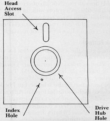
Most computer manufacturers send bits from their computers to disk drives as a steady stream of bits, eight bits per byte, and a fixed number of bytes per stream. At the end of a stream are two more bytes called a checksum of cyclic reduncancy check (CRC). These two bytes are usually the sum of all the previous bytes in the stream. On reading the stream, the checksum can be recomputed from the stream and compared with the checksum recorded on the diskette at the end of the stream. If there is a mismatch, an error has occurred somewhere in the stream.
OSI does not follow this format. They treat disk communication as an asynchronous communication line. In other words, except for the speed of the bits, the computer sends bits to the disk drive in the same way it sends bits to a modem: through a special serial port called an Asynchronous Communication Interface Adapter (for short, an ACIA, UART, or just serial port). OS65D requires 11 bits to be recorded on the diskette for each eight-bit byte. The first bit is a start bit indicating that the byte is beginning. The next eight bits (bits 2-9) are the actual data byte. The tenth bit is a parity bit indicating whether the byte contains an even or an odd number of value one bits. The last bit is a stop bit indicating the end of the byte.
The disadvantages of this method are twofold. First, it is nonstandard. OSI owners cannot interchange disks made by computers of other manufacturers. Second, OSI can store only 8/11 as much on a disk as other manufacturer's computers.
The advantages are reliability and simplicity. An inexpensive ACIA performs many chores simplifying software and hardware. No cyclic redundancy checks are needed. Each byte can be individually checked for an error by the ACIA. If there is a disk error, usually all but a few bytes can be recovered correctly using the EXAMINE command of OS65D. Other systems make recovery much more difficult. A bit error can cause all bits in a stream to shift by one. In other words, bit two of a byte may be read as bit one, and bit zero of a byte may be read as bit seven in the previous byte. OS65D does an excellent job of error detection. It is a shame that, in a system with such excellent opportunities for error recovery, OS65D has absolutely none. If BASIC encounters a disk error, a program stops with a terse error message.
Track Format
Figure 2 gives the actual data format for an OS65D diskette track. Note that the Track 0 format differs from all other tracks. In particular, Track 0 can only be used by the bootstrap ROM. Track 0 contains the major portion of OS65D and is given added protection by this scheme, but I believe OSI blundered in choosing this format. All tracks should be recorded the same way to maximize flexibility.
The data on a track commences 1 ms. past the index hole (about 23 bytes in time at 44 us./byte). Two bytes are written to indicate the beginning of a track. The bytes should be carefully chosen so as to be an unusual combination. OS65D always writes $43 then $57. When the track is read, reading does not commence until the $43 and $57 have been found. A simple encryption method would be to change these bytes. Since the EXAMINE command will even read such a track, this encryption is not terribly secure. OS65U uses different bytes, so OS65U tracks cannot be read by OS65D without minor changes to the operating system.
| Figure 2. | ||||||
| FORMAT FOR TRACKS (>0) | ||||||
| Index Hole | lms. | $43 | $57 | Track # | $58 | 6615 us. |
| $76 | Sector # | # Pages in Sector | That many Pages of Data | |||
| $47 | $53 | Intersector Wait Time | Repeat for each Sector | |||
| FORMAT FOR TRACKS (>0) | ||||||
| Index Hole | lms. | Load vector high | Load vector low | #Pages | ||
| … That many Pages of Data … |
Next the track number is written in binary coded decimal (BCD). This recorded value is always compared with the stored track number in memory to make certain the head is positioned on the correct track. Then a stop byte ($58) is recorded on the disk (this byte is never checked on a read).
This data constitutes the Track Header. On Initialization, a track is erased then the Track Header is written on the Track. This Track Header is not rerecorded at any future read or write.
There is a lull after the Track Header of just under 6.6 ms. (about 149 bytes). This time differs greatly from the time given in the OS65D GUIDE. You will see why in the following discussion.
During a sector seek operation, a "previous sector" length number P is saved. This value is set to four if we seek Sector 1 (otherwise the "previous sector" length number would be zero, which is not allowable). Then a subroutine waits px800 μs. The OS65D GUIDE says that between Sector N and Sector n + 1 there is a gap of px800 μs. This is not quite correct. After the end of a sector, OS65D waits quietly for px800 μs. The write function is then switched on. A further 185 μs. is allowed to pass. Then the erase function is switched on. We now wait an additional px800 μs. before starting to write data. In other words, the time from the last byte of sector n to the first byte of sector n + 1 is about pxl600+ 185 μs. For Sector 1, p is taken to be four. In all other cases, p is the length (in pages, i.e. multiples of 256 bytes) of the "previous sector."
This description requires modification. It applies to systems with a 1 MHZ clock. On cold start, OS65D measures the timing on a serial port to calculate the clock speed. (Remember, a 300 baud port must remain 300 baud no matter what the clock speed.) Then a timing constant in the 1 ms. subroutine is set. However, this calculation does not affect the 100 us. routine used in sector spacing. (I assume this clock versatility is the reason for the NMHZ in the title of this version of OS65D.) In other words, the 100 us. routine is really a 100/T us. routine where T is the clock speed in MHZ.
This calculation accounts only for the wait loops in intersector timing. In addition, there is quite a bit of inline code which adds to intersector timing. This timing can be calculated. A crude estimate would be to add an additional 30 us. after each sector. In other words, the sector spacing is
(pxl600 + 215)/T
where T is the clock speed in MHZ, and p is the number of pages in the preceding sector. Your disk does not necessarily write diskettes identically with mine, though either computer should read the other's diskettes.
All of this says there is some kind of empty space between the end of the Track Header and the start of Sector 1. Each sector is completely rewritten each time it is addressed in a write operation. A sector is written as follows.
We put a sector start code ($76) on the disk. Next comes the sector number s, then the sector length p in pages (each page is 256 bytes). The smallest unit of disk storage in OS65D is one page. The sector number s is verified on a read operation with the value in memory. The sector length is used on read to calculate the number of bytes to load from the disk.
Now comes the actual data. The amount of data is px256 bytes where p is the number of pages in the sector. After this data comes two end check bytes ($47, $53) marking the end of a sector. Thus the sector if 5 + px256 bytes long. The gap between sectors has already been described. Each succeeding sector follows the same format. This format is pictured in Figure 2. This discussion does not apply to Track 0.
Before discussing Track 0, let's make a few calculations. We assume we have 8" floppies and a 1 MHZ clock (this latter enters in only for the timing between sectors). We discuss how many and what kind of sectors may be put on a track. The discussion is important for the following reason: on a write operation, OS65D checks for the index hole when seeking a Track Header. This keeps the computer from "hanging" on uninitialized tracks (i.e. tracks without a Track Header). In writing sector n, the computer must read the preceding sectors l, 2,…, n-l. For each of these, while the computer is searching for the sector start code, it also watches for the index hole to come around again (also to avoid "hanging" on a sector seek). After the start of the preceding sector, the computer no longer checks to see if we pass the index hole. The reason for this is simple. At 1 MHZ with 8" floppies there is just not enough time between input or output bytes from the disk to check for the index hole and to do all the other operations required during a read or write operation.
If the index hole passes, we are back to the beginning of the track. If 1 ms. passes, we're over the Track Header again. Obliterating the Track Header destroys the readibility of the Track. Experienced programmers may salvage matters using the EXAMINE command, but this is not a task you want to face. Moral: Don't pass the index hole a second time on a write operation.
If you're not a whiz at algebra, skim over this part until we start drawing conclusions.
We wish to derive a formula for the time from the index hole to the time the head stops writing on the diskette after sector n. If this time occurs before a second appearance of the index hole, then n sectors will fit on a track. We must account for all the time from the first appearance of the index hole until the write function is switched off after the last sector.
The disk spins at 360 rpm. Thus one revolution takes 166,667 μs. The disk data clock runs at 250 KHZ. In particular, each bit takes four μs. Since an OSI byte uses 11 bits, 44 μs. are required per byte. If we could pack a track, this means we could fit 3,787 bytes on a track. But a track is not packed. It is formatted, and we must calculate the formatting time.
We use 1000 us. from the index hole to the Track Header. The Header is four bytes long using 176 us. more. As we have seen, from the Track Header to the start of Sector one, we use 4×1600 + 215 or 6615 us. In particular, 7791 μs, are spent between the index hole and the start of Sector one.
Each sector contains an integral number of pages. Thus, all sectors contain, as an aggregate, p pages. Each byte takes 44 us. and there are 256 bytes per page. Thus all these pages account for 11264xp us.
Each sector has five extra bytes. Thus, for n sectors, we have 220xn μs.
Next we must account for all the wait time after each of the n sectors. Recall that the wait from one sector to the next is qx 1600 + 215 μs. where q is the number of pages in the preceding sector. Since we assume n sectors are on a track, there are only n-1 spaces between n sectors. If the last sector has r pages, then the preceding n-1 contain p-r pages altogether. Thus, the total intersector wait time is 1600x(p-4) + 215x(n-l) μs.
Finally, we must account for the time after the last sector is written until the write and erase functions are switched off. Write and erase continue for 600xr us. after the last byte is written. Then write is switched off and erase continues for 525 μs. more before it too is switched off. This total trailing time is 525 + 600xr μs.
By adding all our derivations, we can make the following statement. For 8" floppies with a one MHZ clock, the total recording time for n sectors is
t(μs.) = 8101 + 12864xp - 1000xr + 435xn
where p is the total number of pages of data in the sectors and r is the number of pages in the last sector.
Remember, OS65D must run on all OSI machines, so this formula gives the "worst case" which must always be satisfied. In Table 2 you will see a few ‘upper limit’ values tabulated (dt gives the ‘time remaining’ in the track).
Recalculate t for your system. A minifloppy spins at 300 rpm. and the data clock is 125 KHZ. Experiment with a few values for n and p in the formula. Try actually recording this amount on a disk. Be sure to use an empty diskette track. What is wrong with filling the blank space between the index hole and the Track Header with data? (Think about $43, $57.)The maximum allowable number (plus one) of pages per sector in OS65D is stored in $27ED. You may wish to change this for your experiments.
Notice that OSI recommends a maximum of 13 sectors when only one sector is written on a track, and eight sectors (12 sectors in early GUIDES) if more than one sector is written on a track. The early GUIDE value is "just barely wrong." The later value is obviously a shot in the dark meant to be conservative. It is probably the case that many drives would accept 12 single page sectors in a track. But even 11 sectors, including 12 pages, leaves very little room for errors.