Interfacing A BSR X-10 AC Remote Control System To Your PET
C. W. Ward
Hazelwood, MO
The January 1980 issue of BYTE magazine published an article by Steve Ciarcia entitled "Computerize a Home." In this article Mr. Ciarcia described a method of expanding his home security system to include control of all the lights and AC outlets in the house. In his words, "This expansion seems to be a contradiction considering previous concern over wiring costs. It would appear that every AC outlet would have to be directly wired to the computer through relays or some remote control capability would have to be added to each light and appliance."
It is this latter approach that is the basis for this and Mr. Ciarcia's article: more specifically, interfacing a BSR X-10 AC Remote Control System to a computer. His approach differs however, in that it proposes building a relatively simple, but not so inexpensive, hardware interface between his computer (a Radio Shack TRS-80 Model I) and the BSR X-10 command console. This article proposes a software oriented solution. In terms of hardware, it requires no more than the connection of an ultrasonic transducer (2 wires) to the appropriate pins of the PET's user port, thus resulting in an even lower cost. It should be noted that the concept applies to any system with an available output port (one line). The machine language program would require rework depending upon the speed of the system's clock (the PET has a 1 megahertz clock) and the number of cycles per instruction.
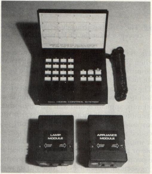
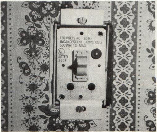
The BSR X-10 system consists of a group of electronic devices that control the electrical environment inside and outside of of your house. Lights can be turned on and off, dimmed or brightened. Plug-in appliances, television sets, and stereos can be turned on or off. No special wiring or complex installations are involved. The system is expandable by adding more modules, a cordless controller or other command consoles. The system is shown in photo 1 and photo 2. The components are: The command console, the wall switch module, the appliance module, and the lamp module. A cordless controller (not shown) is available, but is not an integral part of the system being presented in this article.
The BSR X-10 system is marketed by Sears, Penneys and Radio Shack, to mention just a few, under slightly different product names. The components of one vendor's system are interchangeable with those of another, with one very notable exception. There are two different types of command consoles: one model (X10-014301) that can be remotely controlled with a hand held cordless controller, and one model that cannot! The command console that can be controlled by the hand held cordless controller is a requirement. The buyer should make certain that the BSR X-10 system purchased includes this particular model.
The BSR X-10 components are quite inexpensive when compared to the cost of the alternatives. The command console sells for $39 while each remote module sells for $15.
The command console of the system operates by sending coded signals through the house wiring to the lamp, appliance, and wall switch modules. Each remote module monitors these transmissions and responds only when its particular code is sent. The coded signals sent by the command console can be initiated by physically pressing a key on the console or by the receipt of a series of tone bursts in the proper sequence through the ultrasonic receiver section. This series of tone bursts would typically be transmitted by the hand-held cordless controller as a result of pressing one of its twenty-two keys. Its keyboard contains sixteen unit keys, numbered one through sixteen, each corresponding to the number set (or dialed) on the remote lamp, appliance, or wall switch module. The keyboard also contains six command keys labeled and defined as follows:
| ON | Sends "TURN ON" command to selected module. |
| OFF | Sends "TURN OFF" command to selected module. |
| DIM | Sends "DIM" command to selected lamp or wall switch module. |
| BRIGHT | Sends "BRIGHTEN" command to selected lamp or wall switch module. |
| ALL LIGHTS ON | Sends "TURN ON" command to all lamp and wall switch modules simultaneously. (Does not affect appliance modules.) |
| ALL OFF | Sends "TURN OFF" command to every module, including appliance modules. |
The user then selects a given lamp, appliance or wall switch module by pressing the appropriately numbered unit key and initiates the desired function by pressing the appropriate command key. This action actually transmits two separate messages to the command console.
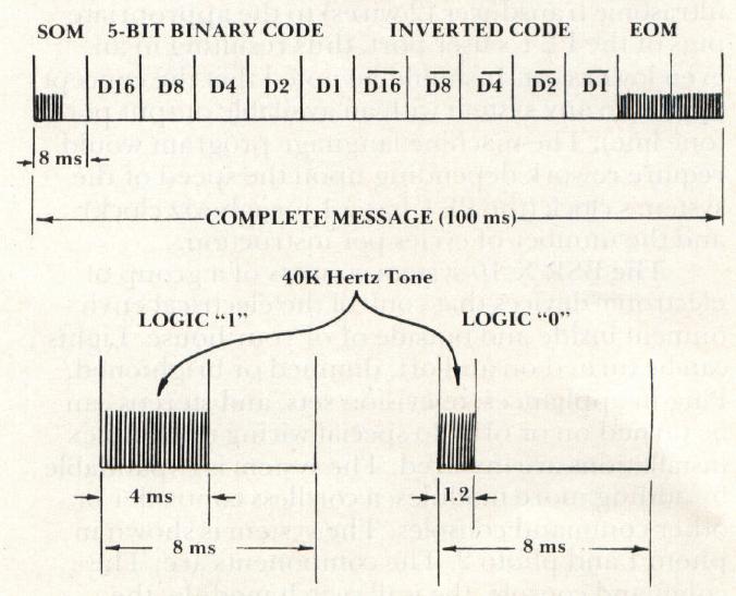
Figure 1 describes the format of the coded messages (tone bursts) sent by the cordless controller to the command console via ultrasonnic communication. Each of the twenty-two keys on the controller has a unique 5-bit binary code (see table 1). A single message is made up of a start-of-message (SOM) code, one 5-bit binary code, the logical inversion of that 5-bit binary code, and an end of message (EOM) code. One message is approximately 100 ms in length and is composed of thirteen segments. Each segment is 8 ms in length. The start of message segment consists of a 4 ms 40K hertz tone followed by a 4 ms period of silence. Each segment of the data (5-bit binary code or inverted 5-bit binary code) consists of a 4 ms 40K hertz tone for a logic 1 or a 1.2 ms 40K hertz tone for a logic 0, followed by a silent period of the appropriate length. The end of message code consists of two 8 ms segments, each containing a 40K hertz tone for the complete duration. All messages use exactly the same format; only the 5-bit binary data codes vary.
Safety is the primary consideration. There is no hazard in using the controller or any of the remote modules as long as their cases remain intact. The BSR X-10 is Underwriters Laboratories listed. The PET must remain electrically isolated from the command console at all times. This is accomplished with communication in the form of ultrasonic sound transmitted through space by the transducer attached to the PET's user port. In essence, the PET software will simulate the activity of the hand-held cordless controller.
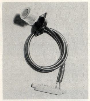
The hardware task consists of soldering the two wires of an output transducer to pin C (PAO) and pin A (GND) of a receptacle for the PET's parallel user port. The cable between the transducer and the receptacle is typically shielded (see photo 3).
Several sources for obtaining the 40K hertz transducer follow:
MASS A Laboratories Inc.
Hingham, MA
Part number TR-89
The Micromint
917 Midway
Woodmere, NY 11598
Part number 1002
The transducer shown in photo 2 was obtained from a local electronics surplus store, giving reason to believe that the 40K Hertz transducer is relatively common. Another possible source would be the service department of a local TV dealer. Most remote TV controllers today make use of ultrasonic transducers.
The effective range of the transducer is approximately twenty feet. When testing, various distances from the command module should be tried. Experience with several different transducers has shown that some failed to activate the console if positioned extremely close while others worked only in such a position.
Program 1 shows a simple BASIC driver program that serves only to demonstrate how the machine language sub-program should be used. Line 100 requests the user to enter the decimal data code for a given remote unit or a given function. If valid, the value is poked into location zero and the machine language program is executed. This is repeated several times to ensure success. During testing, this loop count should be increased. The REM statements in the program merely document the unit and function codes. If the program is listed just prior to running, the codes will be readily available (displayed on the PET screen) during the demonstration.
Program 2 is an assembled version of the 6502 machine language program required to generate the thirteen 8 ms segments that make up a single message. The routine begins by initializing the data direction register (E84316) for VIA data output port A (E84F16). PA0 is defined as an output line and PA1 through PA7, although not actually used, are defined as input lines. The remainder of the mainline routine is subdivided into segments containing calls to appropriate subroutines to produce the 8 ms segment in question. Labels on each of the subdivisions correspond to the field labels in figure 1 describing the complete message. The 40K hertz tone on the transducer is produced by alternating the logic value (0 or 1) of pin C (PA0) of the user port at a rate of 40,000 cycles per second. This is accomplished by the machine language subroutine labeled "X40KHZ". The period of time that a given 40K hertz tone is produced is determined by the number of times the subroutine continues to loop. The calling program sets register X accordingly. The periods of silence are accomplished by calling the machine language subroutine labeled "DELAY". Again, the period of time is determined by the number of loops. The instruction timings are given in the comments field of the assembled instructions in each subdivision.
| 5-BIT BINARY CODE | ||||||
| UNITCODE | D16 | D8 | D4 | D2 | D1 | DECIMAL EQUIVALENT |
| 1 | 0 | 1 | 1 | 0 | 0 | 12 |
| 2 | 1 | 1 | 1 | 0 | 0 | 28 |
| 3 | 0 | 0 | 1 | 0 | 0 | 04 |
| 4 | 1 | 0 | 1 | 0 | 0 | 20 |
| 5 | 0 | 0 | 0 | 1 | 0 | 02 |
| 6 | 1 | 0 | 0 | 1 | 0 | 18 |
| 7 | 0 | 1 | 0 | 1 | 0 | 10 |
| 8 | 1 | 1 | 0 | 1 | 0 | 26 |
| 9 | 0 | 1 | 1 | 1 | 0 | 14 |
| 10 | 1 | 1 | 1 | 1 | 0 | 30 |
| 11 | 0 | 0 | 1 | 1 | 0 | 06 |
| 12 | 1 | 0 | 1 | 1 | 0 | 22 |
| 13 | 0 | 0 | 0 | 0 | 0 | 00 |
| 14 | 1 | 0 | 0 | 0 | 0 | 16 |
| 15 | 0 | 1 | 0 | 0 | 0 | 08 |
| 16 | 1 | 1 | 0 | 0 | 0 | 24 |
| Table 1: Cordless controller push-button codes and decimal equivalents. | ||||||
| 5-BIT BINARY CODE | ||||||
| COMMAND | D16 | D8 | D4 | D2 | D1 | DECIMAL EQUIVALENT |
| ALL OFF | 0 | 0 | 0 | 0 | 1 | 01 |
| ALL LIGHTS ON | 0 | 0 | 0 | 1 | 1 | 03 |
| ON | 0 | 0 | 1 | 0 | 1 | 05 |
| OFF | 0 | 0 | 1 | 1 | 1 | 07 |
| DIM | 0 | 1 | 0 | 0 | 1 | 09 |
| BRIGHT | 0 | 1 | 0 | 1 | 1 | 11 |
100 INPUT "ENTER CODE";C
110 IF C<0ORC>30 THEN PRINT "INVALID CODE": GOTO 100
120 FOR I = 1 TO 3 : POKE0, C: SYS (31744): NEXT
140 GOTO 100
197 REM ------------------------------
198 REM ******************************
199 REM ------------------------------
200 REM   UNIT   CODE    UNIT    CODE
201 REM ------------------------------
202 REM    1       12       9       14
203 REM    2       28      10       30
204 REM    3        4      11        6
205 REM    4       20      12       22
206 REM    5        2      13        0
207 REM    6       18      14       16
208 REM    7       10      15        8
209 REM    8       26      16       24
210 REM ------------------------------
211 REM FUNCTION  CODE  FUNCTION  CODE
212 REM ------------------------------
213 REM  ALL OFF    1  ALL LITES ON  3
214 REM    ON       5     OFF        7
215 REM   DIM       9    BRIGHT     11
216 REM ------------------------------
217 REM ******************************
218 REM ------------------------------
READY.
The machine language program, as assembled, will load into the high address end of RAM (1C0016). It should be loaded and BASIC's upper memory limit reset prior to loading and executing the BASIC driver program (see a previous COMPUTE! article).
The approach used to time the various functions (ie. the program loops and sequences of instructions to produce the desired periods) does not interfere with the PET's clock nor does the clock interrupt handling software produce any undesired effects on these timing sequences. Turning on a table lamp, then, is as simple as poking a value and executing a machine language program. A sophisticated BASIC program can now be developed using the PET's time-of-day clock. Remote BSR X-10 modules can be placed around the home to control a variety of appliances and lights, and all at a much lower cost!
                ORG X‘0000’
               * PAGE ZERO WORKING STORAGE
0000           CODE       DS    1X        CALLING PARAMETER
0001           ONE        DS    1X
0002           TEMP       DS    1X
               * SYSTEM EQUATES
               DDREG      EQU   X‘E843’   DATA DIRECTION REGISTER
               PORT       EQU   X‘E84F’   VIA DATA OUT PORT A
                          ORG   X‘1C00’
1C00 A901      START      LDX   #1
1C02 8D43E8               STA   DDREG
1C05 8501                 STA   ONE
               *--------------------------SEGMENT 1--------------
1C07 A2A0      SOM        LDX   #160
1C09 20631D               JSR   X40KHZ     4000,8
1C0C A24F                 LDX   #79        2
1C0E 20791D               JSR   DELAY      6,3962
1C11 0502                 ORA   TEMP       3
               *--------------------------SEGMENT 2--------------
1C13 A500      D16        LDA   CODE      3
1C15 2910                 AND   $10       2
1C17 F00D                 BEQ   OVER1     3*
1C19 A2A0                 LDX   #160      2
1C1B 20631D               JSR   X40KHZ    6,4,4000,8
1C1E A24F                 LDX   #79       2
1C20 20791D               JSR   DELAY     6,3962
1C23 4C331C               JMP   D8        3
1C26 A230      OVER1      LDX   #48        2
1C28 20631D               JSR   X40KHZ    6,4,1200,8
1C2B A287                 LDX   #135      2
1C2D 20791D               JSR   DELAY     6,6762
1C30 4C331C               JMP   D8        3
              *---------------------------SEGMENT 3--------------
1C33 A500     D8          LDA   CODE
1C35 2908                 AND   $08       (TIMINGS SAME AS ABOVE)
1C37 F00D                 BEQ   OVER2
1C39 A2A0                 LDX   #160
1C3B 20631D               JSR   X40KHZ
1C3E A24F                 LDX   #79
1C40 20791D               JSR   DELAY
1C43 4C531C               JMP   D4
1C46 A230     OVER2       LDX   #48
1C48 20631D               JSR   X40KHZ
1C4B A287                 LDX   #135
1C4D 20791D               JSR   DELAY
1C50 4C531C               JMP   D4
              *---------------------------SEGMENT 4--------------
1C53 A500     D4          LDA   CODE
1C55 2904                 AND   $04       (TIMINGS SAME AS ABOVE)
1C57 F00D                 BEQ   OVER3
1C59 A2A0                 LDX   #160
1C5B 20631D               JSR   X40KHZ
1C5E A24F                 LDX   #79
1C60 20791D               JSR   DELAY
1C63 4C731C               JMP   D2
1C66 A230     OVER3       LDX   #48
1C68 20631D               JSR   X40KHZ
1C6B A287                 LDX   #135
1C6D 20791D               JSR   DELAY
1C70 4C731C               JMP   D2
              *---------------------------SEGMENT 5--------------
1C73 A500     D2          LDA   CODE
1C75 2902                 AND   $02       (TIMINGS SAME AS ABOVE)
1C77 F00D                 BEQ   OVER4
1C79 A2A0                 LDX   #160
1C7B 20631D               JSR   X40KHZ
1C7E A24F                 LDX   #79
1C80 20791D               JSR   DELAY
1C83 4C931C               JMP   D1
1C86 A230     OVER4       LDX   #48
1C88 20631D               JSR   X40KHZ
1C8B A287                 LDX   #135
1C8D 20791D               JSR   DELAY
1C90 4C931C               JMP   D1
              *---------------------------SEGMENT 6--------------
1C93 A500     D1          LDA   CODE
1C95 2901                 AND   $01       (TIMINGS SAME AS ABOVE)
1C97 F00D                 BEQ   OVER5
1C99 A2A0                 LDX   #160
1C9B 20631D               JSR   X40KHZ
1C9E A24F                 LDX   #79
1CA0 20791D               JSR   DELAY
1CA3 4CB31C               JMP   NOTD16
1CA6 A230     OVER5       LDX   #48
1CR8 20631D               JSR   X40KHZ
1CAB A287                 LDX   #135
1CAD 20791D               JSR   DELAY
1CB0 4CB31C               JMP   NOTD16
              *---------------------------SEGMENT 7--------------
1CB3 A500     NOTD16      LDA   CODE    3
1CB5 2910                 AND   $10     2
1CB7 D00D                 BNE   OVER6   3*
1CB9 A2A0                 LDX   #160     2
1CBB 20631D               JSR   X40KHZ  6, 4, 4000, 8
1CBE A24F                 LDX   #79      2
1CC0 20791D               JSR   DELAY   6, 3962
1CC3 4CD31C               JMP   NOTD8   3
1CC6 A230     OVER6       LDX   #48      2
1CC8 20631D               JSR   X40KHZ  6, 4, 1200, 8
1CCB A287                 LDX   #135     2
1CCD 20791D               JSR   DELAY   6, 6762
1CD0 4CD31C               JMP   NOTD8   3
              *---------------------------SEGMENT 8--------------
1CD3 A500     NOTD8       LDA   CODE
1CD5 2908                 AND   $08       (TIMINGS SAME AS ABOVE)
1CD7 D00D                 BNE   OVER7
1CD9 A2A0                 LDX   #160
1CDB 20631D               JSR   X40KHZ
1CDE A24F                 LDX   #79
1CE0 20791D               JSR   DELAY
1CE3 4CF31C               JMP   NOTD4
1CE6 A230     OVER7       LDX   #48
1CE8 20631D               JSR   X40KHZ
1CEB A287                 LDX   #135
1CED 20791D               JSR   DELAY
1CF0 4CF31C               JMP   NOTD4
              *---------------------------SEGMENT 9----------
1CF3 A500     NOTD4       LDA   CODE
1CF5 2904                 AND   $04       (TIMINGS SAME AS ABOVE)
1CF7 D00D                 BNE   OVERS
1CF9 A2A0                 LDX   #160
1CFB 20631D               JSR   X40KHZ
1CFE A24F                 LDX   #79
1D00 20791D               JSR   DELAY
1D03 4C131D               JMP   NOTD2
1D06 A230     OVER8       LDX   #48
1D08 20631D               JSR   X40KHZ
1D0B A287                 LDX   #135
1D0D 20791D               JSR   DELAY
1D10 4C131D               JMP   NOTD2
              *---------------------------SEGMENT 10---------
1D13 A500     NOTD2       LDA   CODE
1D15 2902                 AND   $02       (TIMINGS SAME AS ABOVE)
1D17 D00D                 BNE   0VER9
1D19 A2A0                 LDX   #160
1D1B 20631D               JSR   X40KHZ
1D1E A24F                 LDX   #79
1D20 20791D               JSR   DELAY
1D23 4C331D               JMP   NOTD1
1D26 A230     OVER9       LDX   #48
1D28 20631D               JSR   X40KHZ
1D2B A287                 LDX   #135
1D2D 20791D               JSR   DELAY
1D30 4C331D               JMP   NOTD1
              *---------------------------SEGMENT 11---------
1D33 A500     NOTD1       LDA   CODE
1D35 2901                 AND   $01       (TIMINGS SAME AS ABOVE)
1D37 D00D                 BNE   OVER10
1D39 A2A0                 LDX   #160
1D3B 20631D               JSR   X40KHZ
1D3E A24F                 LDX   #79
1D40 20791D               JSR   DELAY
1D43 4C531D               JMP   EOM
1D46 A230     OVER10      LDX   #48
1D48 20631D               JSR   X40KHZ
1D4B A287                 LDX   #135
1D4D 20791D               JSR   DELAY
1D50 4C531D               JMP   EOM
              *---------------------------SEGMENT 12 & 13----------
1D53 A2FF     EOM         LDX   #255
1D55 20631D               JSR   X40KHZ
1D58 A2FF                 LDX   #255
1D5A 20631D               JSR   X40KHZ
1D5D A282                 LDX   #130
1D5F 20631D               JSR   X40KHZ
1D62 60                   RTS
               * GENERATE A 40K HERTZ FREQUENCY ON VIA PORT A BIT 0
               * FOR A LENGTH OF TIME DETERMINED BY REGISTER X
1D63 A900      X40KHZ     LDX   #00       2
1D65 ER                   NOP             2
1D66 8D4FE8    LOOP1      STA   PORT      4
1D69 6901                 ADC   #1        2 |
1D6B D8                   CLD             2 |13
1D6C D8                   CLD             2 |
1D6D 8502                 STA   TEMP        3
1D6F 8D4FE8               STA   PORT        4
1D72 6501                 ADC   ONE         3 |12
1D74 CA                   DEX             2 |
1D75 D0EF                 BNE   LOOP1       3 *
1D77 EA                   NOP             2
1D78 60                   RTS             6
               * DELAY FOR A LENGTH OF TIME DETERMINED BY
               * THE VALUE   IN REGISTER X
1D79 0502      DELAY      ORA   TEMP        3
1D7B 0D0200               ORA   TEMP        4
1D7E 20901D    LOOP2      JSR   RETURN      6,6|
1D81 20901D               JSR   RETURN      6,6|
1D84 20901D               JSR   RETURN      6,6|
1D87 0502                 ORA   TEMP        3  |50
1D89 0D0200               ORA   TEMP        4  |
1D8C EA                   NOP               2  |
1D8D CA                   DEX               2  |
1D8E D0EE                 BNE LOOP2         3*
1D90 60    RETURN         RTS               6
1D91                      END START-----------------------------