Basics of Light Pen Operation
Robert A. Peck
Manager,
Technical Support to Advanced Manufacturing Memorex Corporation
Manufacturers of personal computers are attempting to make the computer more easily accessible to the public. In doing so, various means have been tried, such as games, simple home budget programs, and the like. The entry format for each of these had, for the most part, been by means of the keyboard, or a game paddle of some kind.
Just recently, the trend toward light pen "menu" selection for ease of data entry has been tried. Let's look at the actual techniques which could be employed to implement this type of input device on a personal computer. The hardware and software requirements will be discussed here. The reader, after studying these techniques, may be able to construct a working form of a light pen with as little as $5.00 worth of materials.
First a note about the definition of a light pen. It does not emit light... rather it is intended to sense the light of an illuminated area on the TV monitor screen. As a photo-sensitive device, some form of output of the light pen will occur as a result of the electron beam energizing a portion of the phosphor of the screen, thus causing it to glow.
To clarify this a bit further, the picture on a TV screen is not all produced at exactly the same time by a single "photo" flashed on the screen. Instead it is made up of a single electron beam being swept from left to right (and down and up) across the screen, with its intensity varied as it sweeps across the screen, to form the picture we see, one line at a time. In this manner, the sweeping beam produces 30 or 60 complete pictures per second on the TV screen. Our own visual system enables us to perceive the screen as though the entire surface of the screen was continuously lit, thus forming a complete picture. The persistence of the screen, the time it remains bright after the beam has passed a particular location, is minimal for most monitor screens.
Let's act, for the moment, in the same manner that the light pen will act. Imagine, if you will, taking a small cylindrical tube and placing it against the surface of a fully illuminated TV screen. If we place our eyes at the opposite end of this tube, and restrict our vision only to what is at the end of the tube and not to the rest of the screen, we are in a position to make a judgement about what is going on in our narrowly restricted view of the world.
Now we must imagine either that we are able to speed up our ability to perceive rapidly the changing intensity of the light on the area of the screen in front of us or that the beam slows down to our level of perception. Either position is ok for our purposes.
As we are looking into the end of the tube, we will notice that there is no light there most of the time. Specifically the phosphor will only be lit up exactly at the time the beam is striking it, and for a short time thereafter, based on the persistence of the screen. But of course, for the most part, we will be kept in the dark. This will be true at any position on the surface of the screen.
Since we know that we have light for a short time and dark for the rest of the time, it is a yes-no situation and something ideally suited to being handled by the computer. So let's give our eyes a rest and place a lens and a phototransistor within the tube in place of our eye. We know that the phototransistor will produce an output when it sees the light and no output when the light is absent.
How complex must the circuit for the phototransistor be to allow us to make this a useful, reliable device? Well, it depends on the type of selection which we wish to make in the usage of the light pen. We'll soon see that for the largest percentage of potential uses, at least at the hobbyist level, a very simple design will serve most purposes admirably.
In order to grasp the significance of the output/no output capability of the phototransistor, we'll next look at the way the computer or its terminal device is producing the output display which we are seeing on the TV.
Let's say we have a terminal which can display 80 columns by 24 lines of usable character positions on the monitor screen. In the process of output, the scan controller must select, each in turn, line 1 of the character memory, then columns 1, 2, 3, ..., all the way out to column 80. Then it must repeat the line scan for as many TV scan lines a character line is supposed to take up. Then it will go on to the next line of 80 characters, the next, and so forth, going back to the beginning again once all 25 lines have been displayed.
From this, you can see that the scan controller will be continuously fetching characters from the character memory. Thus the different addresses of the different characters will each be available on the address bus of the scan controller at the time that character is being fetched for output.
To put it another way, if our character memory was set up such that line 1 position 1 represented address 0 of the character memory and line 1 position 80 represented character address 79, line 2 position 1 as address 80 and line 25 position 80 as address 1999, we would then have a specific point of reference to use. We now take our light pen and place it on the screen directly over one specific character position which is, let us say, occupied by a single solid block character such as a nonblinking cursor.
Every time the phototransistor sees a light output on the screen, at the exact time it occurs, the scan controller address bus has, on it, the exact address within the scan memory occupied by the character which is producing the light output on the screen.
Just as an example of what this address would mean to us, consider the following example. Suppose that at screen location 400 (first position in line 6) we place a cursor character followed by the description .. "CHECKBOOK BALANCER" and at location 800 in the scan memory we placed another cursor character labeled "TREK", we can place the light pen over the cursor character representing the specific program which we wish to have called in next and will expect the light pen scan program to provide us with the data required to do it. In this case when the light pen senses an output, the address of either position 400 or 800 will be on the scan position address bus, ready to be picked up for use by our program. We know that if our program finds 400 on the bus, it must next call in the Checkbook Program. Conversely, if it finds 800 on the bus, it must retrieve the Startrek Program.
Now if we wanted to do so, we would add some additional hardware to our terminal which would act, in association with the phototransistor output, to capture the address present on the bus at the time a light output is sensed. As an exercise, let's examine some of the hardware this would require.
First we need something to capture the scan address from the controller bus and a way to transfer it to the data bus of the computer. A set of three 74175's could be used here. Each is a 4-bit tri-state latch, where the input (capture side) would be connected to the scan memory data bus and the output (storage side) would be connected to the computer data bus for later retrieval. The control lines for the latches would have to be connected in some manner to the light pen through a flip-flop of some kind to assure only a single sampling of the address from the scan counter per application of the light pen to the screen. The tri-state control lines would be connected to the address decoders of the computer so that it could retrieve any one of the three 4-bit stored parts of the scan address after it was triggered.
It might, at first glance, seem a pretty straightforward approach to follow, but let's look at a few of the drawbacks. The first would be the critical control of the level of light intensity sensed by the pen. Specifically, it could possibly be accidentally triggered either by an outside source of light, or by the phosphor persistance (as little as there is) when we first place the pen against the surface of the screen. In either case, the address we sense on the scan control bus does not really represent the actual address of the sample point we are trying to isolate. This might entail some special circuitry to be added to sense only the rising edge of the beam light intensity, where that rising edge has a specific rise time, and therefore not trigger on an outside incandescent light source operating on a 60 Hz sine wave.
To complicate matters further, even though we succeeded in developing this type of edge sensitive equipment, we still run into some problems with fluorescent light sources in the area, in that these have a very fast rise time and have a phosphor afterglow as well. Both items make the light from the fluorescent vary in a manner similar to that of the TV screen. Our software could, of course, compensate for this, but combined with the hardware requirements, we have selected a really complex task. One more area of difficulty, just to mention it here, is the inability to accurately sense the difference in address locations between two adjacent, or very nearly adjacent, squares on the screen unless special circuitry is added for the rise-edge, as described above.
Fortunately, there is a way to absolutely minimize the amount of circuitry needed to establish a workable light pen, along with a way to minimize the complexity of the software which has to go along with it. In addition, the pen needs only to accept a source of power and ground from the computer, and will need only a single bit input port to operate fully. Some manufacturers suggest the use of the same paddle input for the light pen. Below is described the technique which can accomplish this form of operation.
The best features of this technique are the simplicity of the software required and the non-critical nature of the components of the light pen, as well as the non-critical nature of the level adjustments required. We also have an easy way of compensating for any external light source which may have an effect on the pen, and actually ignore it. Let's examine this technique now.
First, let us attack the problem of light sensitivity adjustment. It is proposed that, for this method we will work with, the pen need only be able to distinguish between the presence or absence of illumination within a selected square on the screen. If we are working within a range of light or no light, you can see that we will have a wide degree of adjustment available and still allow the pen to operate perfectly well.
With the original example, let's say we had placed a menu selection box at both scan memory locations 400 and 800 and assume also we are using the simple-form light pen which plugs into the game paddle input. Instead of using a hardware-based scan technique, we will use a software based scan as follows.
Assume for example that we have placed the pen over the square at scan location 800 and we begin our scan. Both the square at 400 and at 800 appear illuminated at this time. Therefore if the light pen is pointing to either one of them, during the period of time of the sweep of the beam across the screen, the light pen will put out a series of pulses coincident with the presence of the beam in the area occupied by the pen.
Now we can begin our scan by replacing the selector box at scan memory location 400 with a blank space (no output on the screen at this point). We will then go to the light pen input and stay in a loop for about 1/60 or 1/30 second and find out if, during that loop, there were any light pulses output. If there were still output light pulses, it means that we had not turned off the square over which the light pen is resting now, so we must continue the scan. Then we relight the square at location 400 and proceed to replace the square at 800 with a blank space. We will again loop through the test program area to determine if there have been any light pulse outputs during the time that location 800 was turned off. If no outputs were sensed during this time, we know we have found the correct location where the light pen is sitting.
We can then take the address we have found this way and use it to control which action is to be done next, just as in the previous hardware controlled case, but here with a good deal less complexity. You can also see that we may have many many menu boxes on the screen and by this means accurately determine exactly which one is being addressed by the light pen. After all, we are the one who is controlling whether the light pen can see a light output from a specific square. So if we turn off a square, and then see that the light pen no longer has an output, we know which square we just controlled and therfore we know what the required operation will be.
We have then substituted a software scan technique for both the complex hardware and complex software the other approach would have required. The primary limit in the number of menu boxes we can use is the amount of time which would be required, at 1/60 or 1/30 sec per box, for the light-pulse-present scan per box on screen. If we have no concern for the time this takes, then there is little reason to limit the number of boxes on the screen except to keep them far enough apart so that the light pen will see the light output from only one at a time, maintaining the wide range of light sensitivity we discussed earlier.
Speaking of light sensitivity, let's discuss the way we'd handle an outside light source and ignore its influence in our selection of the item to be performed. First, a reminder that the single spot on the TV screen we are monitoring is dark for most of the time and is lit by sweeps of the beam only as it passes the area we are monitoring. Now if we consider the outside source of light, it will rather seen to be a continuous sequence of pulses (fluorescent) or a continuous single light level. In the event that there is some continuous pulse interference, we must adjust our software to test that there are no more than X (let's say 50) pulses which occur during a single sweep through our software scan subroutine. This would allow us to ignore such interference as is caused by either a fluorescent or an incandescent source. Certain types of light, such as the sun, cannot be distinguished by the pen as a wave, so are translated as a continuous level, thereby resulting in nearly zero (perhaps one) transitions during the time of a single scan. Thus, we decide that unless greater than one and less than 50 pen state transitions have occurred in one scan, we could probably assume that the visible part of the screen scan probably had been triggered by an outside source, and we can enter into some type of wait state, scanning the pen itself for a time when the correct number of transitions is sensed and, within the wait state loop, also scan our keyboard and any other alternate input device which may be connected to the system and intended for use with the particular program as an input.
A final note about outside light sources; when we have the pen up against the screen, the major influence on the pen will be the light from the screen alone. In this position, the pen will not be affected very much by the outside light.
So thus far we have substituted a software scan for the set of complex hardware. We have used a technique which requires very little translation of address sensed into work to be done. We could probably go into the type of construction required for the light pen itself.
But wait, there seems to be some griping from the back of the room. Yes ... Oh ... OK! The gentleman in the last row says "That's ok for you guys who have the Visible Memory (direct access) display screens, but how about the rest of us who only have the scrolling type of screen?"
A fair question, I agree. All right. A scrolling type of screen is one where everything moves up one notch to make room for the bottom line once the screen is filled. Well, a number of these types of screens have the ability to move the cursor in a relative manner or an absolute manner. If it does have this capability, then the technique still works exactly the same way...we just have to work a little harder. Lets look at a quick example.
We'll print a cursor box followed by a descriptive line on the screen, followed by a blank line, and repeat this for 5 selections. Now to do the cursor scan, we will begin from the lower left (home) cursor position and move-relative-cursor until we get to the position occupied by one of the selector boxes. Then we replace it with a blank space instead. Scan. Are there light pulses present? If not, we've found the light pen position. If so, cursor backspace, put back the selector box, space relative cursor to the next selector box and repeat the process. As you can see, there is no basic change in the procedure, just a slightly different approach.
Sir,... you do have relative cursor?! Ok then, at least we've got one satisfied customer. By the way, you'd probably be interested; the terminal I use on my machine is a scrolling type and thats why I was prepared for that question!
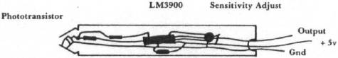
Now for the construction of the light pen itself. We'll need some kind of small cylinder to house it. The cylinder will have to have enough room for the phototransistor itself. And, it should have some room for a small variable resistor and a voltage comparator IC if we want to have it fully self-contained and ready to plug into the game paddle input of our computer.
I have provided a sketch of the proposed construction of the pen, along with the schematic of the one I use. These parts I had were primarily junk-box components, and as a result, my total cost was about $1.00 (plus the software development time). You could probably obtain most of the components for $5.00 or less.
Well, best of luck with your construction and testing. If you develop some interesting applications for your light pen, I would appreciate the chance to hear about them:
Robert A. Peck
Manager, Technical Support to Advanced Manufacturing
MEMOREX CORP
San Tomas at Central Expy MS 10-10
Santa Clara, CA 95052
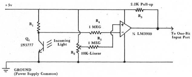
Q1 Mounted in Tip of Pen
R2 Sensitivity adjustment, adjusted so that plus pulses are present while pen is on screen opposite a part of screen which is lit up.
ABOUT THE AUTHOR: Bob has a BSEE from Marquette University and an MBA in Finance and Economics from Northwestern. He has been involved with computers since 1965, and has taught microcomputer courses for Cogswell College in Sunnyvale, CA. He has authored three booklets on hardware and software for the 6502-based SYM-1 Single-Board computer. His assignment at Memorex involves arranging a smooth transition for new products from development engineering to Manufacturing.